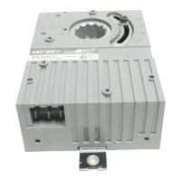
Figure 2: FW-28 legend side and back view
Table 1: FW-28 components
Callout Description
1 35 mm or 1.38 in. DIN rail
2 Enclosure mount
3 Cover screw
4 Hot (H) and Ground (G) terminals
5 Digital Output (DO) terminals
PWR Power LED
ERR Error LED
STS Status LED
TXRX Transmitting or receiving communication LED
DO1 to DO8 Digital output communication LED
RST Reset button. For more information on resetting the
controller, refer to EasyIO FW Series User Reference.
6
SVC Service button
7 Universal Output (UO) and COM (Common) terminals
8 Antenna connectors
9 Serial port terminals
10 DIN rail end clips
11 Antennas
12 Ethernet ports
13 Universal Input (UI) and COM terminals
14 Mounting clips
EasyIO FW-28 Quick Start Guide6
 Loading...