EasyManuals Logo

Johnson Controls S300 Series Hardware Installation

Johnson Controls S300 Series
44 pages
To Next Page IconTo Next Page
To Previous Page IconTo Previous Page
Page #12 background imageLoading...
Page #12 background image
RDR2S-A and I8O4 Hardware Installation Description of Signals
24-10239-596 Rev. D
8
DESCRIPTION OF SIGNALS
All interface signals are connected via plug-in connectors. For a description of
the I/O interface signals, see:
Input Point Signals on page 33
Output Point Signals on page 35
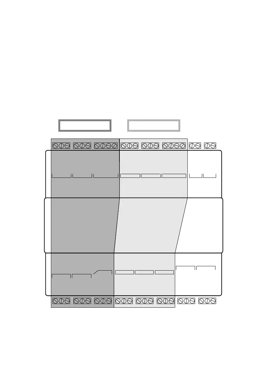
The figures below are outlines of the position of terminal blocks, followed by
detailed drawings.
Figure 4: RDR2S-A Terminal Blocks Outline
READER 1
STRIKE
READER 1
SHUNT
READER 1
READER 2
STRIKE
READER 2
SHUNT
READER 2
PANEL S300 BUS
READER 1 READER 1 READER 1 READER 2 READER 2 READER 2 CAL POWER
RDR2S-A
READER 1 READER 2

Other manuals for Johnson Controls S300 Series

Questions and Answers:

Question and Answer IconNeed help?

Do you have a question about the Johnson Controls S300 Series and is the answer not in the manual?

Johnson Controls S300 Series Specifications

General IconGeneral
BrandJohnson Controls
ModelS300 Series
CategoryControl Unit
LanguageEnglish

Related product manuals