RDR2S-A and I8O4 Hardware Installation Cable Requirements
24-10239-596 Rev. D
21
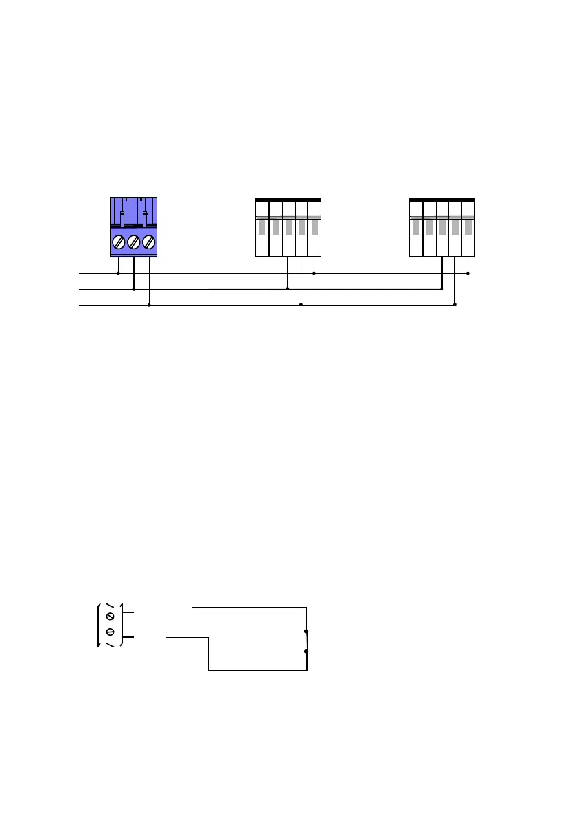
Connecting the COM (Ground) Wire
When daisy-chain connecting an RDR2S-A, wire the devices according
to the following illustration:
Wiring Input Devices
Tamper Switch Wiring
The tamper switch connects to a general purpose input point. To be
operational, the tamper switch must be wired to one of the unused input
points on any RDR2S-A in the enclosure, and programmed in the
controller. Use the PANEL/TAMP connector for this function.
General Input Wiring
The inputs can be used as either 2-state or 4-state inputs. You should
calibrate the inputs depending on the needs of your site.
2-State Inputs Wiring
RDR2S-A or I8O4
Connector (RS-485)
S300 Series
Connector (RS-485)
12
3
45
S300 Series
Connector (RS-485)
12
3
45
COM
RS485-
RS485+

 Loading...


