RDR2S-A and I8O4 Hardware Installation Setup and Adjustments
24-10239-596 Rev. D
33
NOTE: On CK721-A controllers, a write to flash must be performed after
completion of input point/output point disassociation configuration.
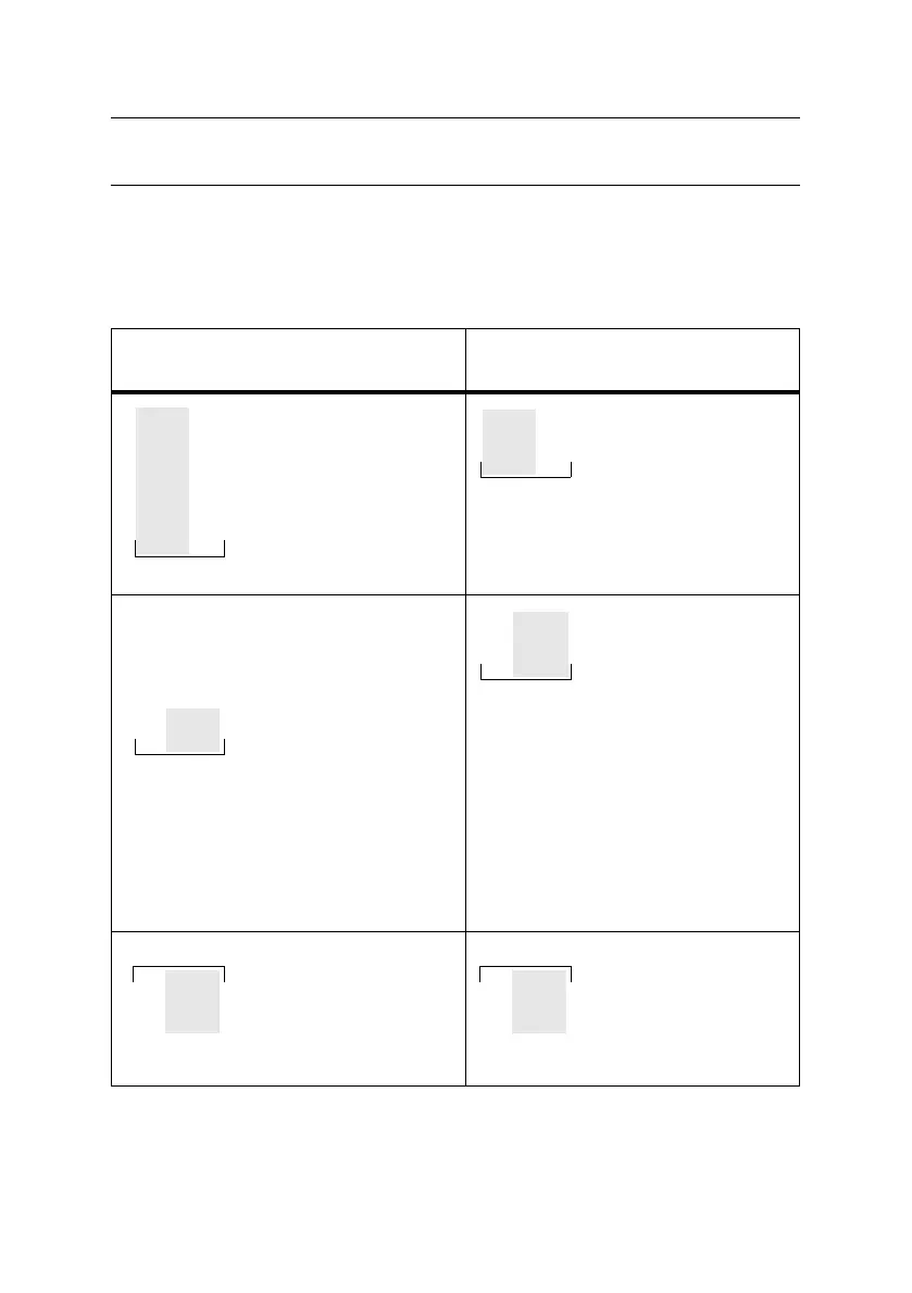
Input Point Signals
Table 7: RDR2S-A and I8O4 Input Points
Application-Specific Use
1
(RDR2S-A only)
General Purpose Use
2
(RDR2S-A with
I/O disassociation or I8O4)
“Reader n Door Contact”
Application Specific Input
Can be calibrated to 2-
state or 4-state.
Wire this input normally
closed.
“Terminal n IN1”
General Purpose Input
Can be calibrated to 2-
state or 4-state.
“Reader n REX”
Application Specific Input
Can be calibrated to 2-
state or 4-state.
2-state auxiliary input is
closed for the “request to
exit” state.
When calibrating the 4-
state auxiliary input,
ensure that the switch is
in the inactive state (not in
the “request to exit” state).
Wire this input normally
open.
“Terminal n IN2”
General Purpose Input
Can be calibrated to 2-
state or 4-state.
“Reader n Spare”
Input Terminal n Input
Point 3
General Purpose Input
Can be calibrated to 2-
state or 4-state.
“Terminal n IN3”
General Purpose Input
Can be calibrated to 2-
state or 4-state.
REX
COM
DOOR CONTACT
READER n
REX
COM
DOOR CONTACT
READER n

 Loading...


