RDR2S-A and I8O4 Hardware Installation Setup and Adjustments
24-10239-596 Rev. D
24
S300/RS485 Connection
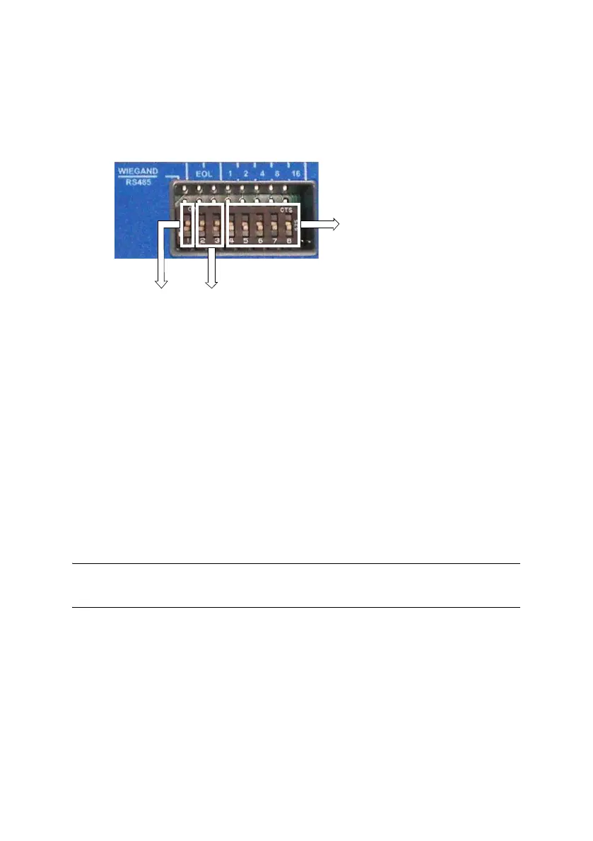
The following figure shows a portion of the top cover of the RDR2S-A or
I8O4 module with adjustable Wiegand/RS485, EOL, and address
switches.
Wiegand/RS485 Switch
Reader Wiegand interfaces (Data0 and Data1) are pulled up to 5VDC by
internal 3.92K Ohm resistors when the Wiegand/RS485 switch is on (up).
When the Wiegand/RS485 switch is off (down), these signal lines are
compatible with RS485 communications.
NOTE: The Wiegand/RS485 switch is used for both readers. Wiegand type and
RS485 type readers should not be mixed on the same RDR2S-A.
Setting the End-of-Line Switches
Network devices at either end of the S300 network must be set as network
terminated devices. This is done with the use of the End-of-Line (EOL)
switches. The RDR2S-A and I8O4 modules have two End-of-Line
switches: SW2 position #2 and SW2 position #3.
Turn both of the module’s switches on (up) or both off (down) according
to the position of the RDR2S-A or I8O4 module on the S300/RS485 bus.
EOL Switches:
SW2 position #2
and SW2 position #3
Wiegand
switch
Address
switches
Note:
The Wiegand/RS485 and EOL switches are ON (up) by factory
default. The address switches are OFF (down) by factory default.

 Loading...


