RDR2S-A and I8O4 Hardware Installation Setup and Adjustments
24-10239-596 Rev. D
27
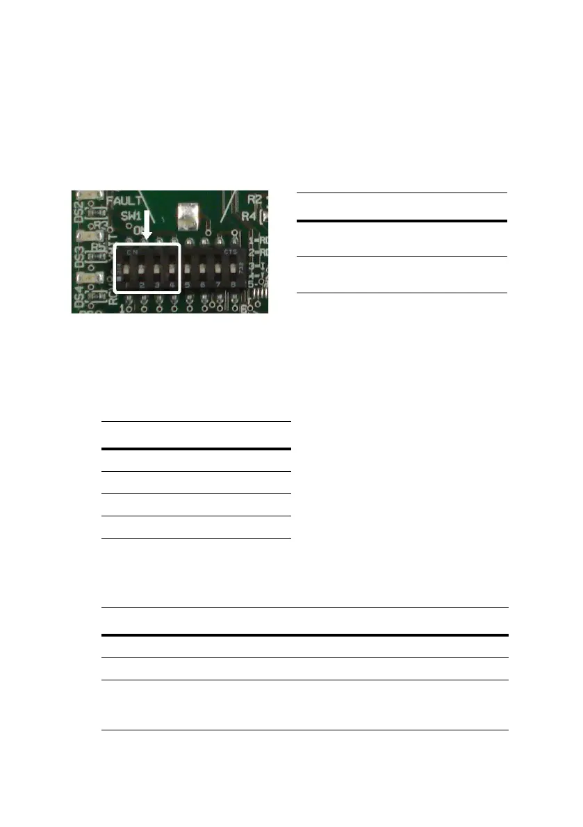
Address Mode Switches (SW1)
The address mode is determined by the position of the address mode
switches (SW1). They are located under the module cover.
Switch positions 1 through 4 determine address mode, switch positions 5
through 8 are not used.
Legacy Address Mode
In legacy address mode individual terminals are enabled as follows:
Based on switch configuration, the module maps its input points as
follows:
Switch ON Description
1 RDR1 Enabled
2 RDR2 Enabled
3 I/O 1 Enabled
4 I/O 2 Enabled
RDR Enabled I/O Enabled Description
Off On RDR map disabled, I/O map enabled
On Off RDR map enabled, I/O map disabled
On On RDR map enabled, I/O map enabled
1
RDR map enabled plus spare and tamper inputs
door contact and REX can be monitored
2
1. The RDR map takes precedence over the I/O map.
2. CK722 controller only.
Address Mode Switch Position
Physical
address mode
All switch positions 1
through 4 are OFF.
Legacy
address mode
Any of switch positions
1 through 4 is ON.

 Loading...


