86
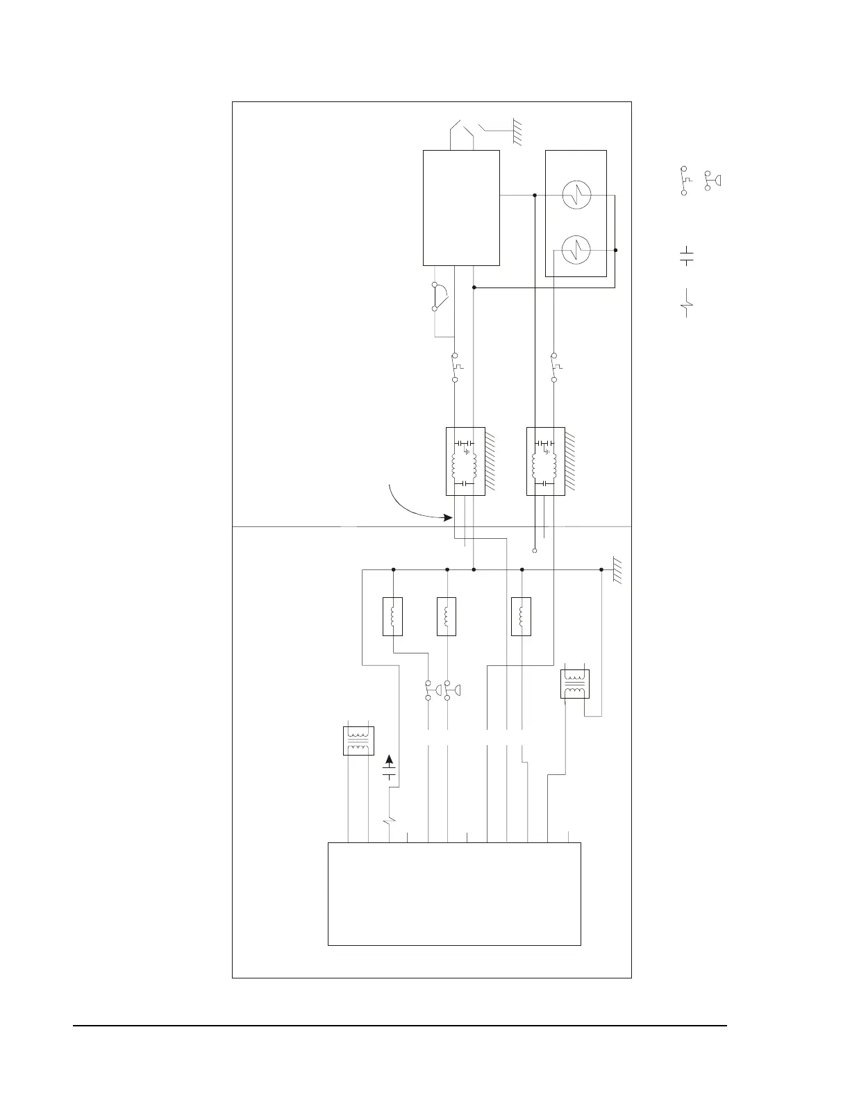
UNT Controller—Unitary (UNT) Controller
Line
Note 1: You may mount the UNT and pilot relay within the rooftop unit's wiring cabinet or externally.
Note 2: Depending on the rooftop unit, these "limit" switches may actually be temperature, pressure, or flow actuated switches.
Note 3: Limit switches depicted in this drawing may be different types (i.e., pressure, temperature, etc.) than those actually used in your
particular unit. In addition, a single switch shown here may represent multiple switches in series in your unit. Do not
bypass or void any safety or limit switches.
Rooftop Unit
UNT
24 VAC
Common
BO8
BO7
BO6
BO5
BO4
BO3
BO2
BO1
TRIACS*
24 VAC
* Discard Triac Jumper
Unit
Transformer
Load
Load Line
Contactor
Contactor
Y2
Y1
W2
Contactor
R
B
Wiring Cabinet
Added
Transformer
To Economizer
1R 1R1
Metal Barrier
W2 W1
2-Stage
Gas
Valve
Stage 2 Stage 1
LoadLoad
LineLine
Ignition Control
R1
THS (24 VAC)
Common
Spark
Flame
Sensing
Chassis
Grounded
Line Filter
Chassis
Grounded
Line Filter
N.C.
Tes t Po i nt
N.C.
Short “Quite” Wires
Between Filter
and Barrier
CS
W1
G
rtop1
Relay
Coil
Relay
Contact
Equipment Limit or
Safety Switches
MV
Gas Heat Section
Figure 39: UNT Directly Driving Loads