UNT Controller—Unitary (UNT) Controller
87
Line
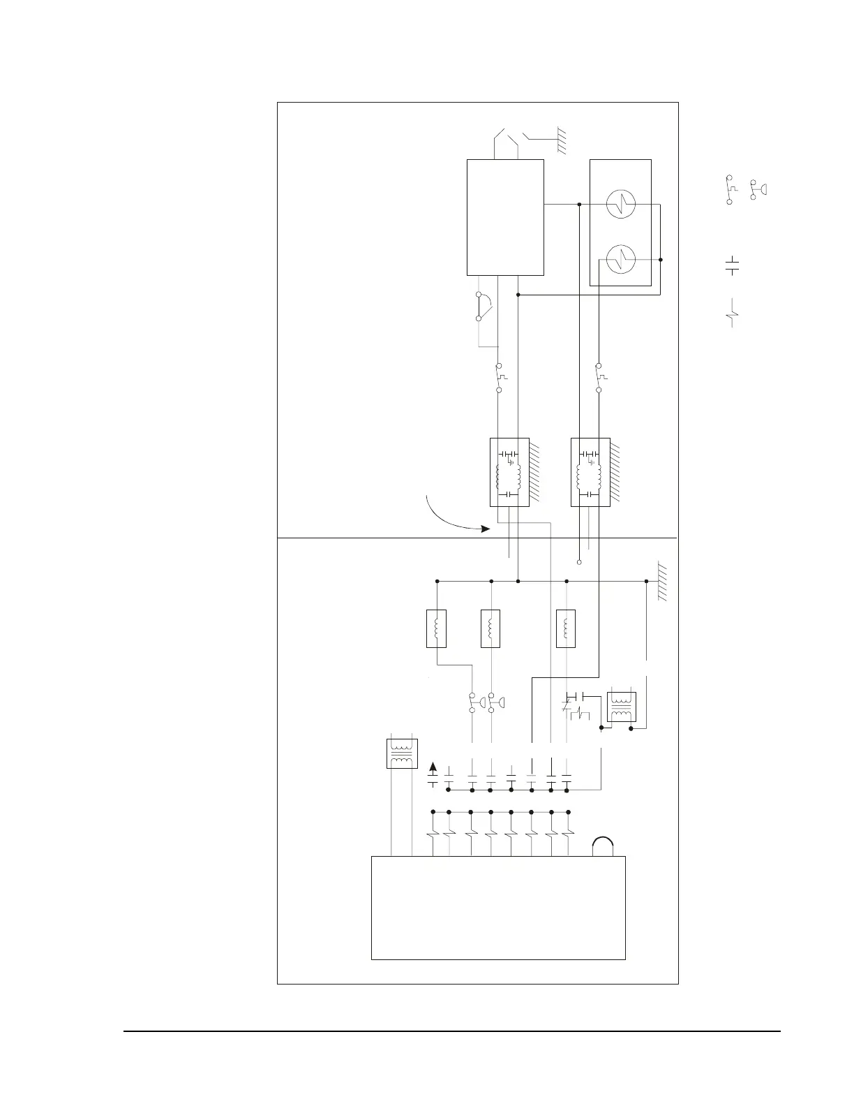
Note 1: You may mount the UNT and pilot relay within the rooftop unit's wiring cabinet or externally.
Note 2: Depending on the rooftop unit, these "limit" switches may actually be temperature, pressure, or flow actuated switches.
Note 3: Limit switches depicted in this drawing may be different types (i.e., pressure, temperature, etc.) than those actually used in your
particular unit. In addition, a single switch shown here may represent multiple switches in series in your unit. Do not
bypass or void any safety or limit switches.
Note 4: See Pilot Relay Important in Item 4 of
Note 5: See Item 5 in
Appendix A, Installation Requirements.
Appendix A, Installation Requirements.
Rooftop Unit
UNT
24 VAC
Common
BO8
BO7
BO6
BO5
BO4
BO3
BO2
BO1
TRIACS*
24 VAC
Load
Load Line
Contactor
Contactor
Y2
Y1
W2
Contactor
Wiring Cabinet
Added
Transformer
To Economizer
1R
1R1
Metal Barrier
W2 W1
2-Stage
Gas
Valv e
Stage 2 Stage 1
LoadLoad
LineLine
Ignition Control
R1
THS (24 VAC)
Common
Spark
Flame
Sensing
Chassis
Grounded
Line Filter
Chassis
Grounded
Line Filter
N.C.
Te s t P oi nt
N.C.
Short “Quite” Wires
Between Filter
and Barrier
CS
W1
G
rtop3
Relay
Coil
Relay
Contact
Equipment Limit or
Safety Switches
R
K25
B
MV
Gas Heat Section
Figure 40: UNT with Pilot Relays