21
2
JOHNSON CONTROLS
FORM 145.05-NOM1 (708)
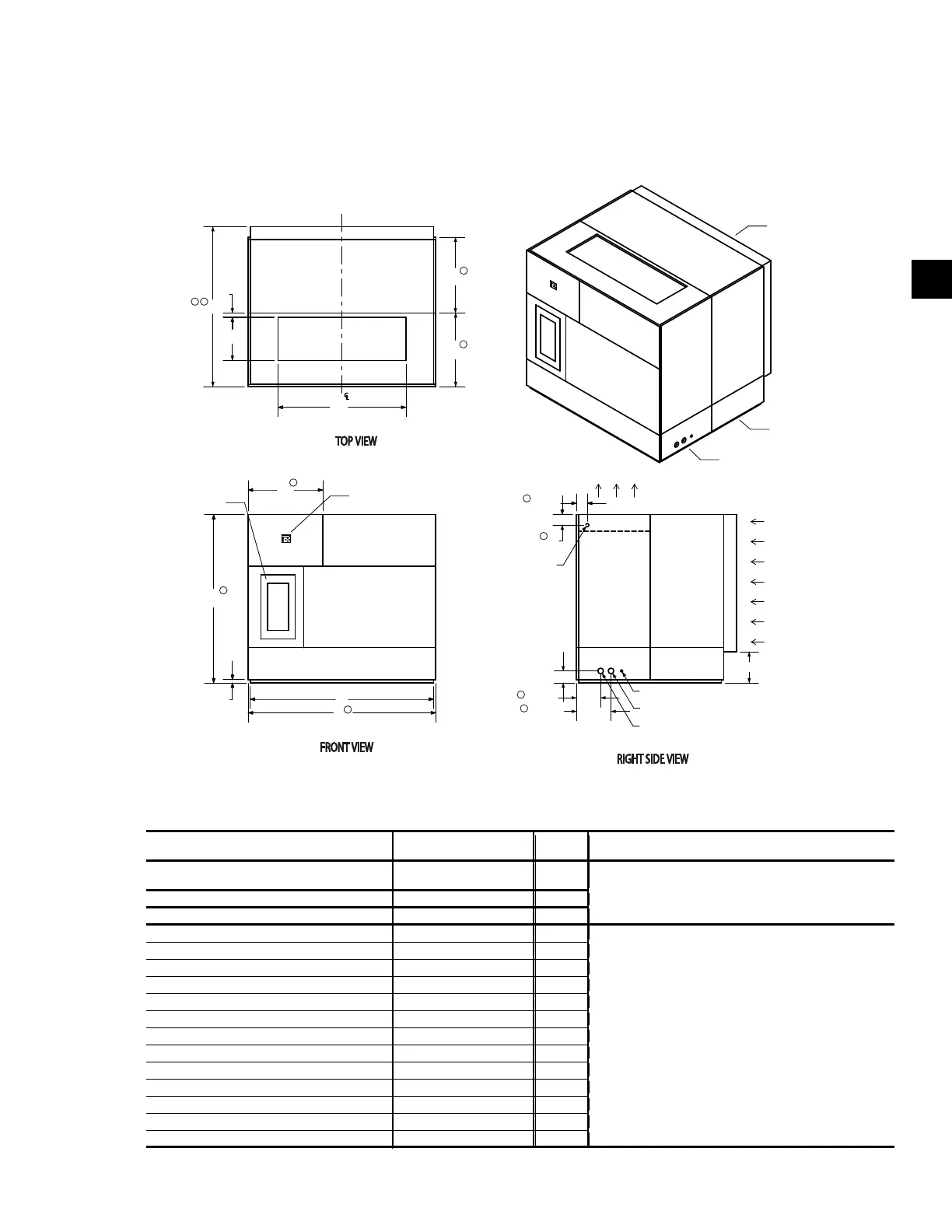
DIMENSIONS AND WEIGHTS
UNIT DIMENSIONS 012, 016, 021, 025 & 032
�
BACK
LEFT
FRONT
RIGHT
B
E
G
F
H
D
C
2"
A
I
Notes:
A. Dimensions do not include handles, latches, lifitng lugs or fastener extensions.
B. All dimensions are
± 0.25".
C. Condenser water supply/return can be located on the left or the right hand side of the unit (right hand shown).
FILTER
SECTION
COIL
SECTION
FAN
SECTION
RETURN AIR
SUPPL
Y AIR
OPERA
TOR
INTERFACE
VARIABLE
FREQUENCY
DRIVE
CONDENSATION DRAIN CONNECTION L
CONDENSATION WATER RETURN M
CONDENSATION WATER SUPPLY M
JXK
14-1/2"
5-5/8"
5-1/8"
5"
Ø
7/8"
POWER CONNECTION
(LEFT HAND SIDE)
11-3/8"
1-1/2"
16-1/4"
1
3
1
1
1
1
1
1
1
1
2
LDO10370
Due to the dedication of continuous product improvement and enhancements, the information/dimensions provided are subject to
change without notice.
Model YSWU 012, 016, 032 NOTES
021 & 025
CFM Range 3,300 to 10,000 8,700– Modular : construction allows the unit to be broken
13,000 into sections to fit thru a 3’ door or small freight elevator.
Tonnage Range 10 to 35 30–45 New/Retrofit : ability to be broken into smaller sections.
Unit Style Modular Modular
A
1
Fan Section Width 34 34 1 Add 1” for 1” access panels
B
1
Coil Section Width 34 34 Add 2” for 2” access panels
C
1 & 3
Installed Width 68 68 Add 3” for 3” access panels
D Discharge Opening Width 20 20
E Discharge Opening Length 40 48 2 Add 2” for 1” access panels
F
1
Installed Height 78 78 Add 4” for 2” access panels
G
1
Electrical Section Width 22 22 Add 6” for 3” access panels
H Base Length (no panels) 50 62
I
2
Installed Length 50 62 3 Add 6” for 4” pre-filters
J Inlet Height 44 58 1/2 Add 12” for 4” pre-filters with 4” final filters
K Inlet Length 60 60 Add 22” for 4” pre-filters and 12” final filters
L Drain Connection 1 1/8 1 1/8
M Condenser Water Supply/Return 2 1/8 2 5/8 CF Consult Factory
All dimensions in inches
 Loading...