101
IGNITION
CHARGE COIL AND SENSOR COIL
5
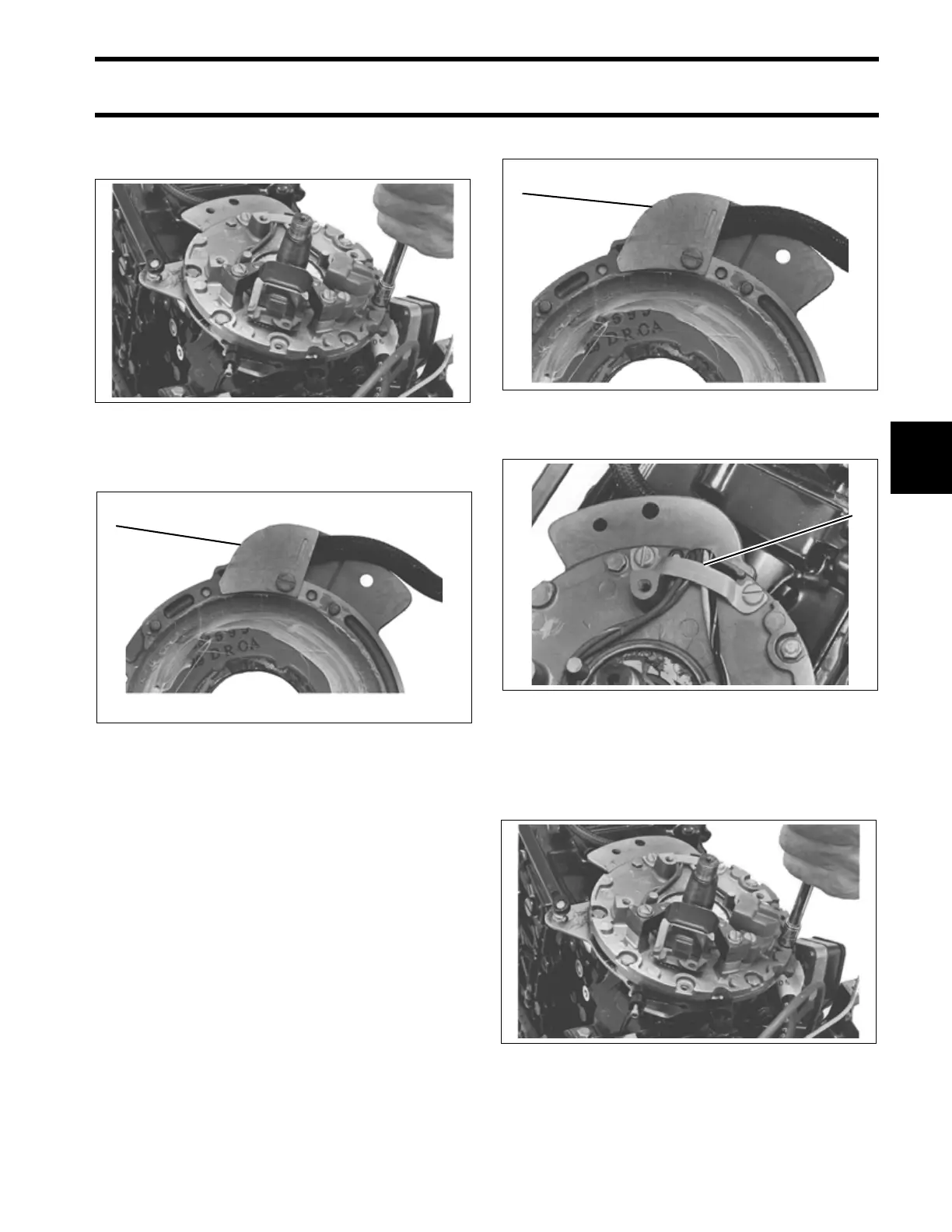
Loosen the ignition plate screws. Lift the ignition
plate from the powerhead.
Remove the plate from the bottom of the ignition
plate.
Remove the leads from the spiral wrap and from
the ignition component.
Installation
Apply Ultra Lock to the threads of the component
retaining screws. Loosely install the new ignition
component on the ignition plate.
Connect and route the leads from the spiral wrap
and from the ignition component.
IMPORTANT: All component leads must be
routed through the clamp and plate in a single
layer, not twisted or crossed over another lead.
Install plate on bottom of the ignition plate.
Install the wire clamp on ignition plate.
Apply Nut Lock to the threads of the ignition plate
screws. Install the ignition plate on the retainer
plate. Torque screws to 25 to 35 in. lbs. (2.8 to 4.0
N·m).
32324
1. Plate 32288
1
1. Plate 32288
1. Wire clamp 32302
32324
1
1