143
POWERHEAD
INSTALLATION
7
Install the intake manifold and leaf valve assembly
using new gaskets. Do not use sealer on these
gaskets. Tighten the screws to a torque of 60 to
84 in. lbs. (7 to 9 N·m).
Install the fuel, ignition, and electrical components
to the powerhead.
INSTALLATION
IMPORTANT: Remove the gearcase to aid in
guiding the water tube into the water pump grom-
met. Refer to Gearcase REMOVAL AND INSTAL-
LATION on p. 167.
Install new powerhead to exhaust housing gasket.
Install dry; use no sealer.
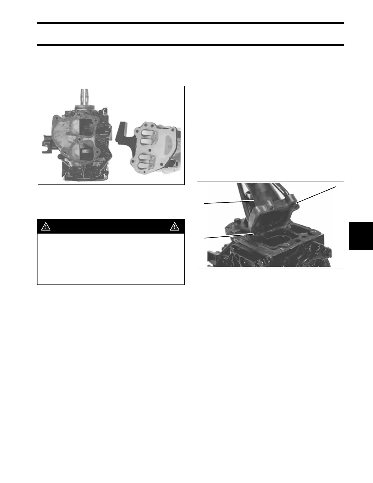
Install both grommets and water tubes in inner
exhaust tube. Center water tube in grommets. Do
not allow water tubes to touch inner exhaust tube.
Position inner exhaust tube on powerhead.
Tighten the screws and torque 60 to 84 in. lbs. (7
to 9 N·m).
Apply a liberal amount of Permatex No. 2 sealer to
the machined diameter of lower crankcase head.
Position the long water tube and the short water
tube as shown prior to installing the powerhead on
the exhaust housing.
Guide the long water tube into the water tube
opening in the exhaust housing and the short
water tube into the opening in the rear of the
exhaust housing as the powerhead is lowered into
the exhaust housing.
32383
WARNING
To prevent possible fire and explosion
under the engine cover, make sure igni-
tion and electrical wires are routed and
clamped in original position; away from
rotating parts which could cut or abrade
wire insulation.
1. Grommets
2. Inner exhaust tube
32402
1
2
1