69
ELECTRICAL
CHARGING SYSTEM TESTS
4
CHARGING SYSTEM TESTS
Charging System Check Chart
Running Alternator Output Test
Disconnect battery cables at the battery.
Remove the rectifier red lead.
Wire a 0 to 40 A ammeter in series with the recti-
fier red lead and the wiring harness red lead.
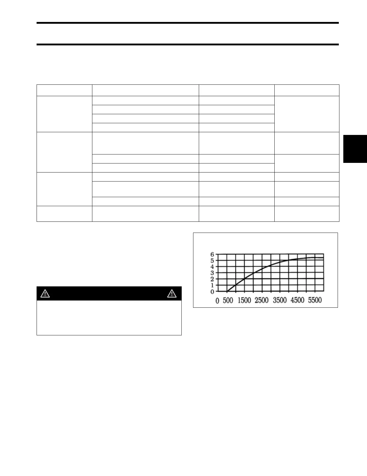
The outboard’s battery should not be fully charged
when beginning this test. Connect the battery
cables and run the outboard in a test tank. Refer
to the output curve to determine the correct out-
put-to-RPM ratio.
• If there is no output or the output is not correct,
refer to Stator Resistance Tests on p. 70 and
Rectifier Resistance Tests on p. 70.
Where to Look Cause Procedure Reference
Battery
Battery defective or worn out Check condition and charge
Accessories Service
Manual
Low electrolyte level Add water and recharge
Terminal connections loose or corroded Clean and tighten
Excessive electrical load Evaluate accessory loads
Wiring
Connections loose or corroded Clean and tighten
Running alternator out-
put test; Stator resis-
tance test
Stator leads shorted or grounded Perform ohmmeter tests
Stator resistance test
Circuit wiring grounded Perform ohmmeter tests
Alternator/stator
Damaged stator windings Perform ohmmeter tests Stator resistance test
Weak flywheel magnets Perform running output tests
Running alternator out-
put test
Damaged stator leads Perform ohmmeter tests Stator resistance test
Rectifier Inoperative rectifier Perform rectifier tests
Rectifier resistance
tests
CAUTION
Guard against any red wire, its terminals,
or the ammeter coming in contact with
engine ground while the engine is run-
ning. Contact could cause arcing.
9.9/15 Model DRC4809
5 Amp Stator
RPM
AMP