71
ELECTRICAL
TACHOMETER CIRCUIT TEST
4
STEP 2
Move ohmmeter lead from engine ground to recti-
fier red lead. Connect the other meter lead to the
yellow/gray rectifier leads. Note the reading.
Reverse the ohmmeter connections or press the
"reverse polarity" button and note the reading.
Perform the same procedure on the yellow and
yellow/blue rectifier leads. Note the readings.
• A high reading in one direction and a low read-
ing in the other direction indicates the diode is
OK.
• Two high readings or two low readings indicate
the diode is damaged.
Replace the rectifier if test results vary.
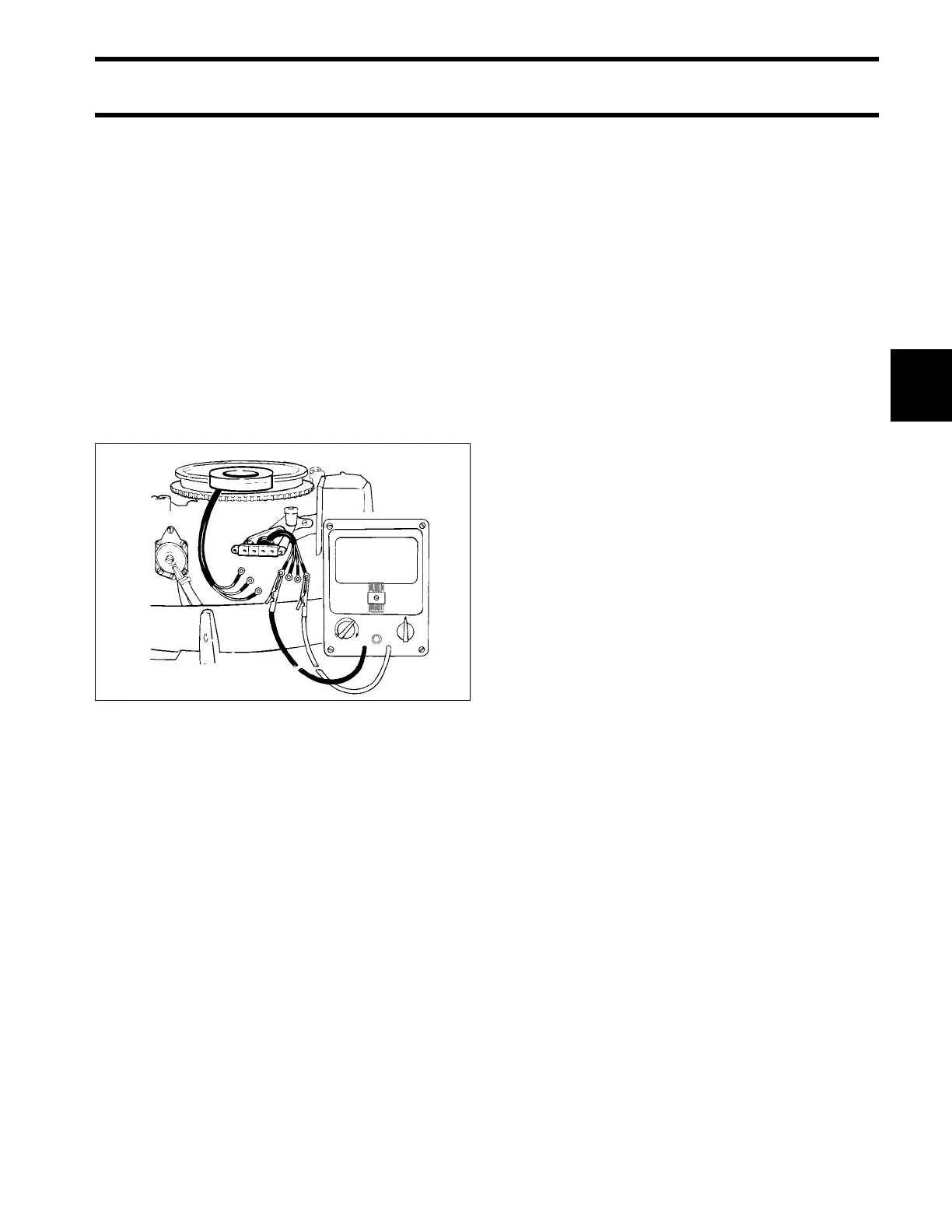
TACHOMETER CIRCUIT
TEST
IMPORTANT: The tachometer circuit is driven
by the stator output. Before proceeding, check
condition of the stator and do the Stator Resis-
tance Tests on p. 70.
Inspect all engine and boat wiring and make sure
connectors are in good condition.
Do the following tests if the tachometer does not
operate.
STEP 1
Set peak-reading voltmeter to “POS” and “50.”
Check voltage at the battery.
• Use this reading as the reference for battery
voltage.
STEP 2
Check for battery voltage between the tachometer
purple lead and black lead at the dash with the
engine NOT running and the key switch ON.
• If the voltmeter shows battery voltage, go to
STEP 3.
• If the voltmeter shows less than battery voltage,
check the purple, purple/red, and black circuits
engine fuse, key switch, and the battery con-
nections.
STEP 3
With the engine NOT running and the key switch
ON, check for battery voltage between the instru-
ment harness gray lead and black lead at the
dash.
• If voltmeter shows 0 V, go to STEP 4.
• If voltmeter shows any voltage replace rectifier.
DR4158
%