75
ELECTRICAL
ELECTRIC STARTER TESTS
4
Voltage Drop Tests
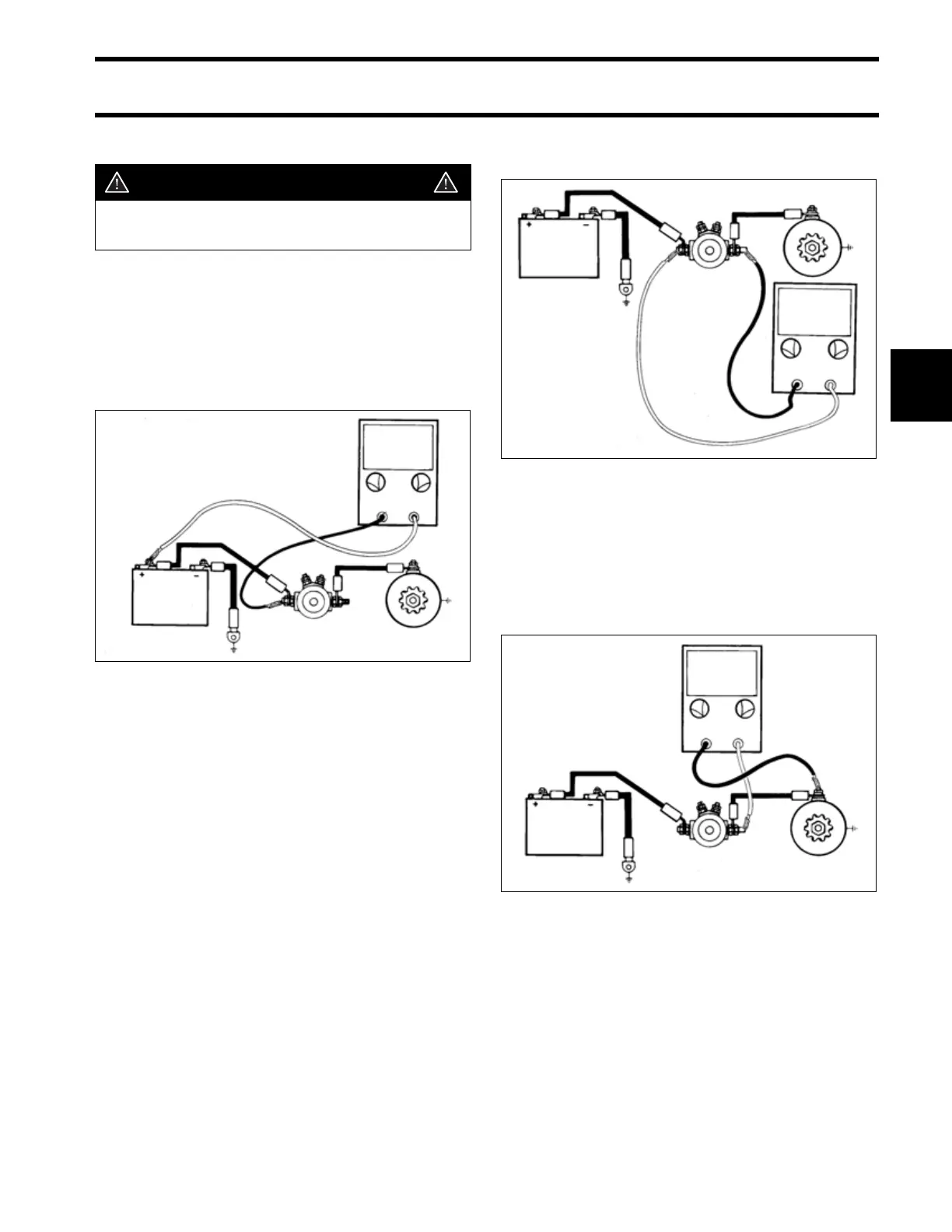
STEP 1
Connect voltmeter positive (+) lead to battery pos-
itive (+) post. Connect voltmeter negative (–) lead
to starter solenoid positive (+) terminal. Turn key
switch to START to crank engine.
• Voltage reading must not be more than 0.3 volt.
IMPORTANT: In STEP 2, connect the voltmeter
leads only while the engine is cranking, or dam-
age to the voltmeter can occur.
STEP 2
Connect voltmeter negative (–) lead to the starter
side of the starter solenoid terminal. While crank-
ing engine, connect voltmeter positive (+) lead to
starter solenoid opposite terminal.
• Voltage reading must not be more than 0.2 V.
Remove voltmeter positive (+) lead from starter
solenoid and stop cranking engine.
STEP 3
Connect voltmeter positive (+) lead to starter sole-
noid, starter lead terminal. Connect voltmeter neg-
ative (–) lead to starter motor terminal. Turn key
switch to START.
• Voltage reading must not be more than 0.2 V.
WARNING
Avoid accidental starting while testing;
twist and remove all spark plug leads.
DRC4029
≤ 0.3V
DRC4030
DRC4031
≤ 0.2V
≤ 0.2V