91
IGNITION
IGNITION SYSTEM TESTS
5
Charge Coil Test
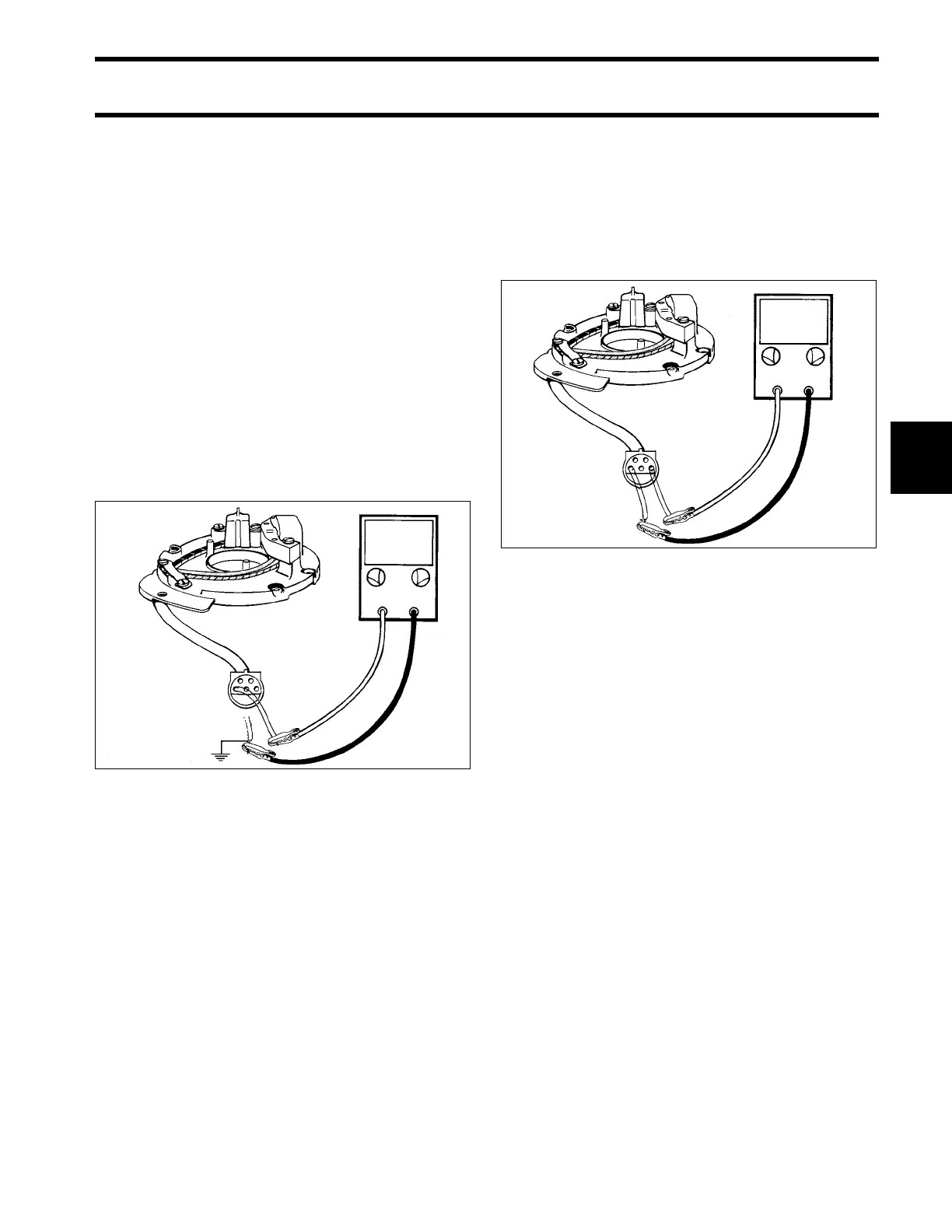
STEP 1
Disconnect 5-pin Amphenol connector between
ignition plate and power pack.
Set peak-reading voltmeter to:
• 9.9/15 – "NEG" and "500."
Alternately, connect voltmeter between ignition
plate connector terminals "A," "D," and a clean
engine ground. Crank engine and observe meter
at each connection.
• Any reading on either test indicates charge coil
or leads are grounded.
• Locate and repair ground, or replace charge
coil.
• If no reading is indicated go to STEP 2.
STEP 2
Set peak-reading voltmeter to:
• 9.9/15 – "NEG" and "500."
Attach voltmeter black lead to ignition plate con-
nector, terminal "A." Attach meter red lead to ter-
minal "D."
Crank engine and observe meter.
• If meter shows 230 V or higher, go to Sensor
Coil Test on p. 92.
• If meter shows less than 230 V, check condition
of wiring and connectors.
• If wiring and connector condition is good, go to
STEP 3.
DR4619
0 V
DR4620
≥ 230 V