96
IGNITION
IGNITION SYSTEM TESTS
Ignition Coil Analyzer Tests
IMPORTANT: When conducting these tests to
the coil, do not exceed its maximum specified
amperage.
Power Test
The ignition coil is tested with normal polarity con-
nections.
Connect tester red lead to the primary terminal of
the coil and the tester black lead to the ground
tab. Connect the high tension lead of the tester to
the coil spark plug lead.
A steady spark, in the tester at or before maxi-
mum specified amperage, indicates a good coil.
Refer to Ignition Coil Specifications on p. 95.
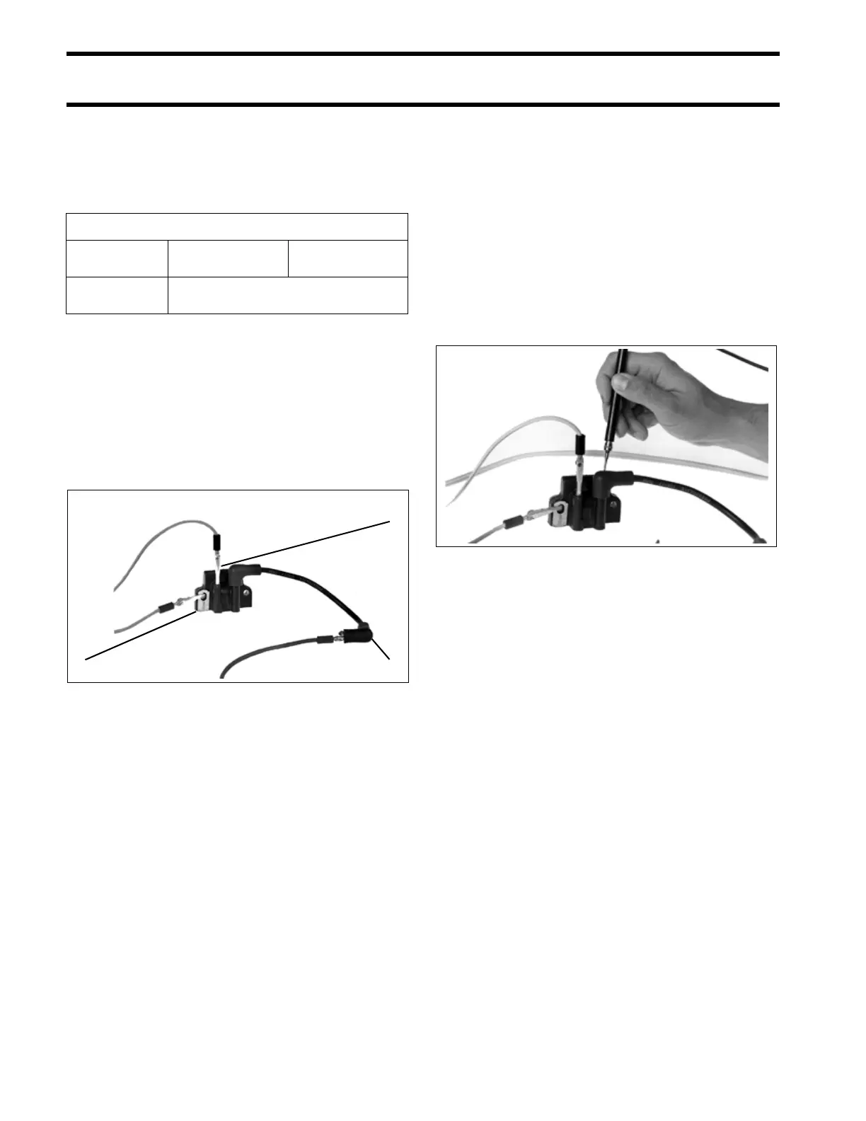
Surface Leakage Test
The ignition coil and spark plug lead should be
tested for leakage or insulation failures using the
ignition analyzer. Leakage is caused by moisture,
cracks, or holes in the coil housing or spark plug
leads.
With the analyzer’s black and red leads still con-
nected from the Power Test, remove the ana-
lyzer’s high tension lead from the coil. Turn on the
analyzer and probe the entire surfaces of the coil,
spark plug lead, and spark plug cover.
Flashover will be apparent wherever insulation
has broken down. Replace any coil or spark plug
lead which shows leakage.
Magneto C.D. Coil Specifications
Operating
Amps (Max)
Merc-O-Tronic
1.5 amps
Stevens
1.1 amps
Analyzer
Polarity
Normal
1. Primary terminal
2. Ground tab
3. Coil spark plug lead
COA4328
1
32
COA4327