6
4 Electrical connection
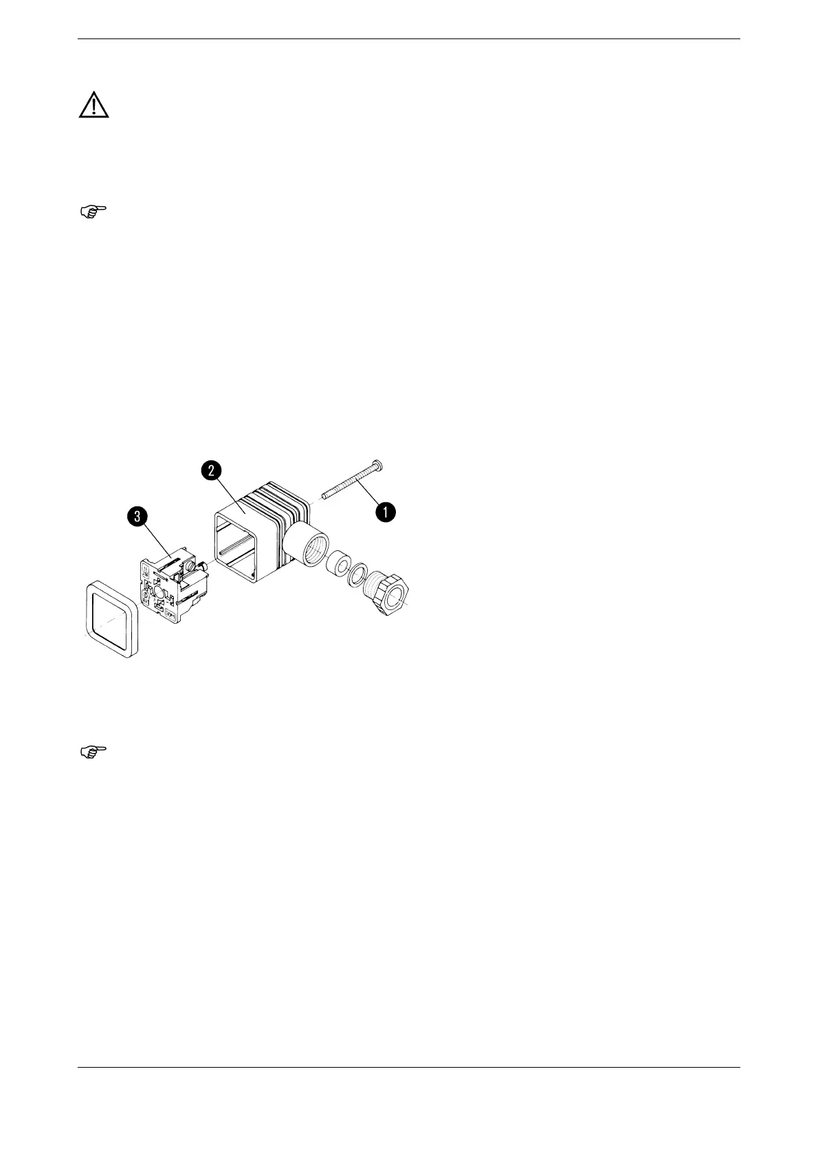
4.1 Assembly of the terminal box
to open up the connector:
✱ Unscrew the screw (1).
✱ Using a small, flat screwdriver, lever the inner part (3) out of the outer part (2) (see marking on the inner
part).
The inner part can be re-assembled and inserted into the outer part in 4 positions 90× apart.
4.2 Installing the attached connecting cable
(Extra code /73)
Pressure transmitters must only be connected by properly qualified personnel!
Terminal box to DIN 43 650, Form A with Pg9 cable gland. Conductor cross-section up to
1.5 mm2 max., external dia. of conductor Ø 4.5 — 7 mm, Protection IP65.
Terminal box to DIN 43 650, Form C with Pg7 cable gland. Conductor cross-section up to 0.75
mm2 max., external dia. of conductor Ø 3.5 — 6 mm, Protection IP65.
The protection specified will only be achieved when the connector is firmly in position with the
corresponding seal.
Minimum bending radius 120 mm (fixed cable run).
The cable must not be compressed. The end of the cable must be located in a dry room to
avoid condensation. It is best to route the cable directly into a switch cabinet.
When lengthening the cable, ensure that pressure equilibration is provided while avoiding the
ingress of moisture.