41
6 Parameterization
6 Paramet erizatio n
The designation "Parameter level" is used in the setup program.
The default settings are shown in bold in the tables.
6.1 Parameter blocks
The following table shows the parameters in a parameter block. The same parameters are also available
for the second parameter block.
Depending on the controller type configured, certain parameters may be omitted or ineffective.
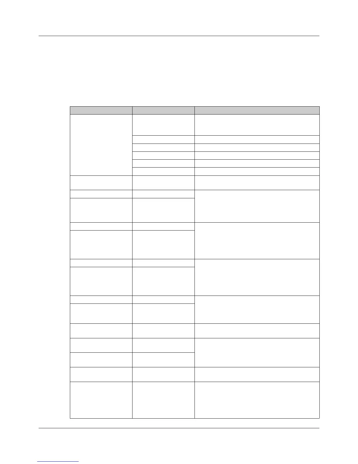
Parameter Selection/text/value Description
Control structure 1 These settings determine the control structure
(transmission behavior) and relate to the first con-
troller output.
P P controller
I I controller
PI PI controller
PD PD controller
PID PID controller
Control structure 2 (see: Control structure
1)
These settings apply to the second controller out-
put for a three-state controller.
Xp1 proportional band 0 to 9999 Value for the proportional band
The controller structure has no effect if Xp = 0 (be-
havior identical to limit value monitoring)!
For a continuous controller, Xp must be > 0.
Xp2 proportional band 0 to 9999
Tv1 derivative time 0 to 9999 (80) The derivative time (in seconds) influences the dif-
ferential component (D component) of the control-
ler output signal.
The effect of the D-term increases as the deriva-
tion time increases.
Tv2 derivative time 0 to 9999 (80)
Tn1 reset time 0 to 9999 (350) The reset time (in seconds) influences the integral
component (I component) of the controller output
signal.
The greater the reset time, the less effect the I
component has.
Tn2 reset time 0 to 9999 (350)
Cy1 cycle time 0 to 9999 (20) The cycle time (in seconds) should be chosen so
that the energy supply to the process is as contin-
uous as possible without overloading the switching
elements.
Cy2 cycle time 0 to 9999 (20)
Xsh contact spacing 0 to 999 Spacing between the two control contacts of a
three-state controller and three-step controller
Xd1 switching differen-
tial
0 to 999 (1) Hysteresis for a switching controller with propor-
tional band Xp = 0
Xd2 switching differen-
tial
0 to 999 (1)
TT actuator time 5 to 3000 (60) Control valve running time range (in seconds)
used for a three-step controller
Y0 working point -100 to +100 (0) Working point correction (in percent) for a P or PD
controller (correction value for the output level)
If the actual value has reached the setpoint value,
the output level corresponds to the working point
Y0.