7 Configuration
56
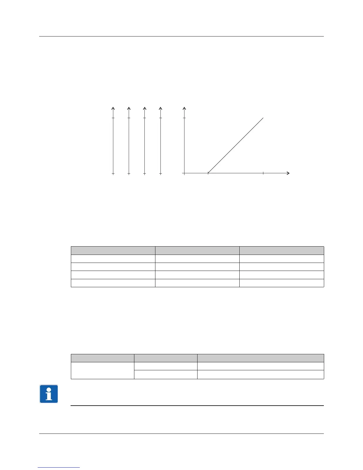
Scaling start, scaling end
An input signal range is assigned to the physical output signal range by scaling. If, for example, a tem-
perature with a range from 150 °C to 500 °C (input signal range) is issued via the analog output with sig-
nal type 0 to 20 mA (output signal range), the zero point is set to 150 (corresponds to 0 mA) and the end
value is set to 500 (corresponds to 20 mA).
The default setting corresponds to an input signal range of 0 to 100 (for example, an output level of 0 %
to 100 % for a controller output).
The following graphic shows the scaling for the example above with different output signals (y-axes).
Response in case of a fault
The behavior in the event of deviation above or below the measuring range (out of range) can be con-
figured. The settings made there also apply for probe/conductor breaks or probe/conductor short-cir-
cuits. This results in a safe state for operation in the event of an fault.
The following table shows the fixed values that are output in the event of a fault - with the corresponding
configuration. The specifications in brackets are limits that apply according to NAMUR recommendation
NE 43.
Behavior after power on
A voltage of 0 V is output during the device's initialization phase (depending on the configuration). Once
the initialization is complete, the output signal depends on the signal of the source and the configured
signal type.
7.7 Digital inputs
The device is equipped with two digital inputs that are provided to connect a potential-free contact.
NOTE!
Digital input 1 can only be used as an alternative to digital input 3.
If digital input 3 (logic output 0/14 V) is activated by assigning a signal source, digital input 1 is inactive.
Signal type Low value High value
0to10V 0 V 10.7 V
0to20mA 0mA 22 mA
4 to 20 mA 3.4 mA (≤ 3.6 mA) 22 mA (≥ 21 mA)
2...10 V 1.7 V (≤ 1.8 V) 10.7 V (≥ 10.5 V)
Parameter Selection/text/value Description
Inversion No Input signal not inverted.
Yes Input signal inverted.