7 Configuration
54
Example
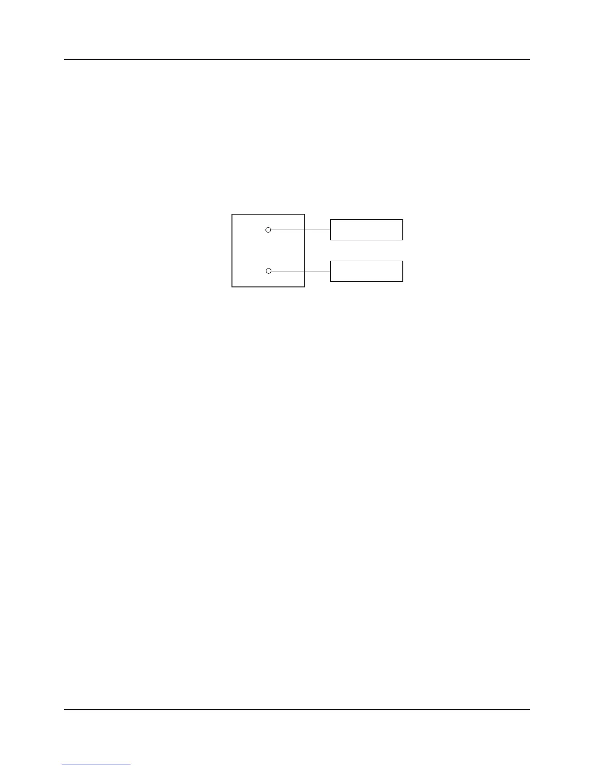
The temperature inside a furnace is measured with an RTD temperature probe connected to the device.
The measured value displayed by the device deviates from the actual temperature as a result of the sen-
sor temperature drifting. The amount of deviation is different at the lower measuring point (start value)
and at the upper measuring point (end value), meaning a measured value offset correction is not suit-
able. The actual temperature (reference value) is determined using a reference measuring device.
Actual start value: 15 °C (measured value)
Target start value: 20 °C (reference value)
Actual end value: 70 °C (measured value)
Target end value: 80 °C (reference value)
(1) Display values
(2) Reference values
(3) Furnace
(4) Sensor in RTD temperature probe
Performing fine adjustment
1) Switch off fine adjustment.
2) Run up first working point (lower measuring point, value as low and constant and possible). Read
the measured value on the device, read the reference value on the reference measuring device.
Note both values.
3) Run up second working point (upper measuring point, value as high and constant and possible).
Read the measured value on the device, read the reference value on the reference measuring de-
vice. Note both values.
4) Switch on fine adjustment, enter device's measured values from the first and second working point
(actual start value (15.0) and actual end value (70.0)); then enter the reference measuring device's
reference values from the first and second working point (target start value (20.0) and target start
value (80.0)).
The following diagram shows the changes in the characteristic line caused by the measured value offset
(point of intersection with the x axis as well as the gradient) based on the values from the example above
(x = reference value, Y = display value).