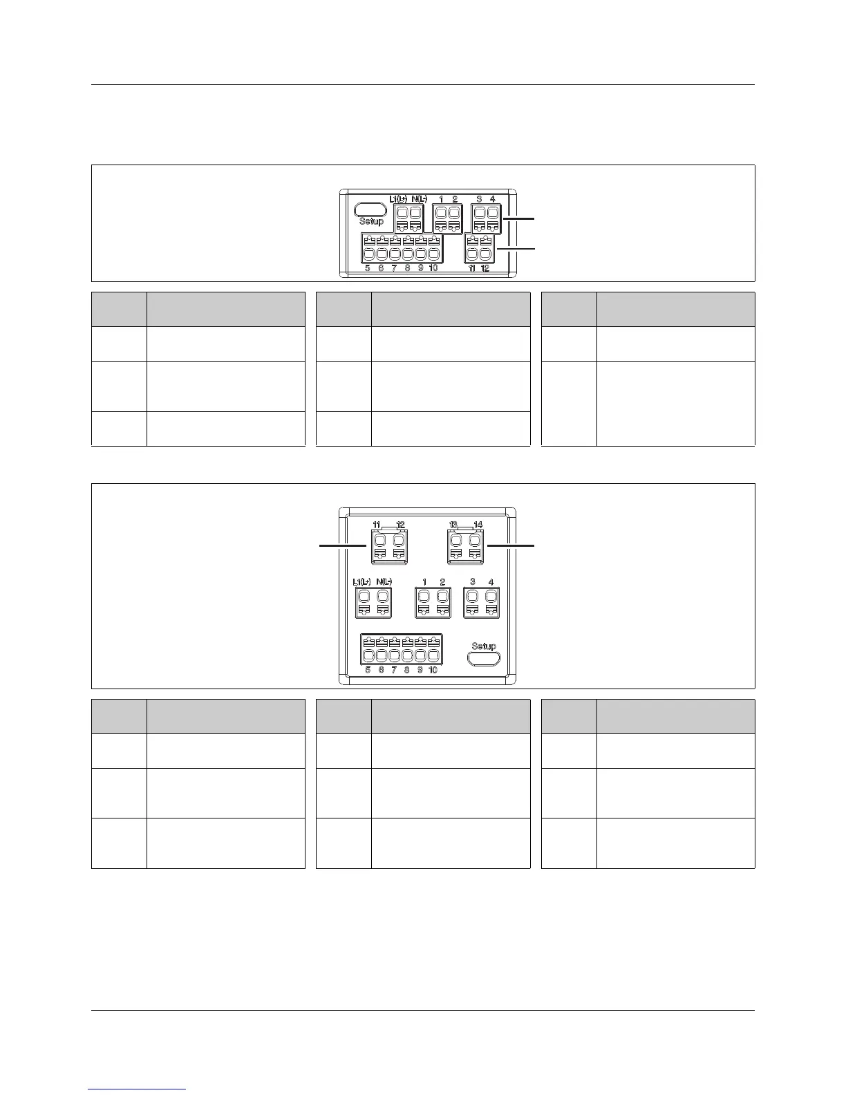
Termi-
nals
Connection Termi-
nals
Connection Termi-
nals
Connection
1, 2 Output 1 (relay) 8, 10 Input 2 (for potential-free
contact)
L1(L+),
N(L-)
Voltage supply
3, 4 (2) = option 2: output 2 (re-
lay, logic or analog output)
9, 10 Input 1 (for potential-free
contact) or output 3 (logic
output)
Setup
(USB)
PC (setup program)
5-8 Analog input 11, 12 (1) = option 1: RS485 in-
terface
Type 702111 (48 mm × 48 mm)
Termi-
nals
Connection Termi-
nals
Connection Termi-
nals
Connection
1, 2 Output 1 (relay) 8, 10 Input 2 (for potential-free
contact)
13, 14 (2) = option 2: output 5 (re-
lay, logic or analog output)
3, 4 Output 2 (relay) 9, 10 Input 1 (for potential-free
contact) or output 3 (logic
output)
L1(L+),
N(L-)
Voltage supply
5-8 Analog input 11, 12 (1) = option 1: output 4 (re-
lay, logic output) or RS485
interface
Setup
(USB)
PC (setup program)
 Loading...


