57
7 Configuration
NOTE!
Digital input 2 can only be used if the analog input has not been configured with signal type 0(2) up to
10 V.
7.8 Digital outputs
The device has a digital output (logic output 0/14 V) and up to two relay outputs (normally open contact).
On top of that, up to four additional digital outputs are optionally available depending on the device type
(relay, logic 0/14 V, PhotoMOS relay).
NOTE!
Digital input 3 can only be used as an alternative to digital input 1.
If digital input 3 (logic output 0/14 V) is activated by assigning a signal source, digital input 1 is inactive.
Behavior after power on
The outputs are not active during the device's initialization phase (depending on the configuration). Once
the initialization is complete, the output signal corresponds to the signal of the source (inverted if neces-
sary).
7.9 Controller
7.9.1 Controller configuration
The general features of the controller are defined in this menu.
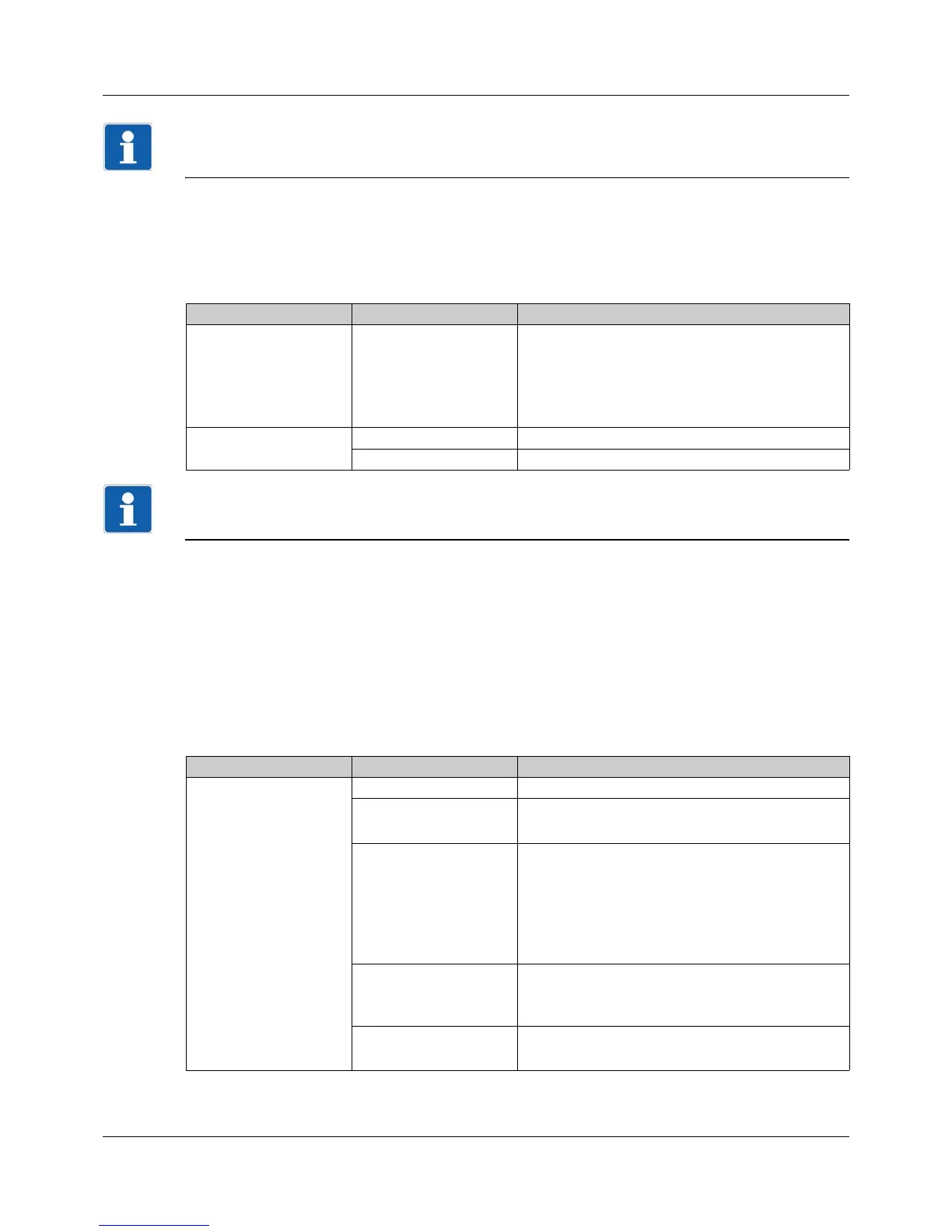
Parameter Selection/text/value Description
Source Digital selector
No selection
Signal that is issued at the digital output.
Default setting for digital output 1:
controller output 1 (digital)
In the event of "No selection" the output signal
does not correspond to the active status.
Inversion No Output signal not inverted.
Yes Output signal inverted.
Parameter Selection/text/value Description
Controller type Off Controller disabled
2-P controller Two-state controller
Controller with a switched output
3-P controller Three-state controller
Controller with two switched outputs (for example,
for heating/cooling)
The combination of a continuous (e.g., for heating)
and a switched output (e.g., for cooling) is also
possible.
3-P step controller Three-step controller
Controller with two switched outputs (for motor ac-
tuator)
Continuous controller Continuous controller
Controller with a continuous output (analog signal)