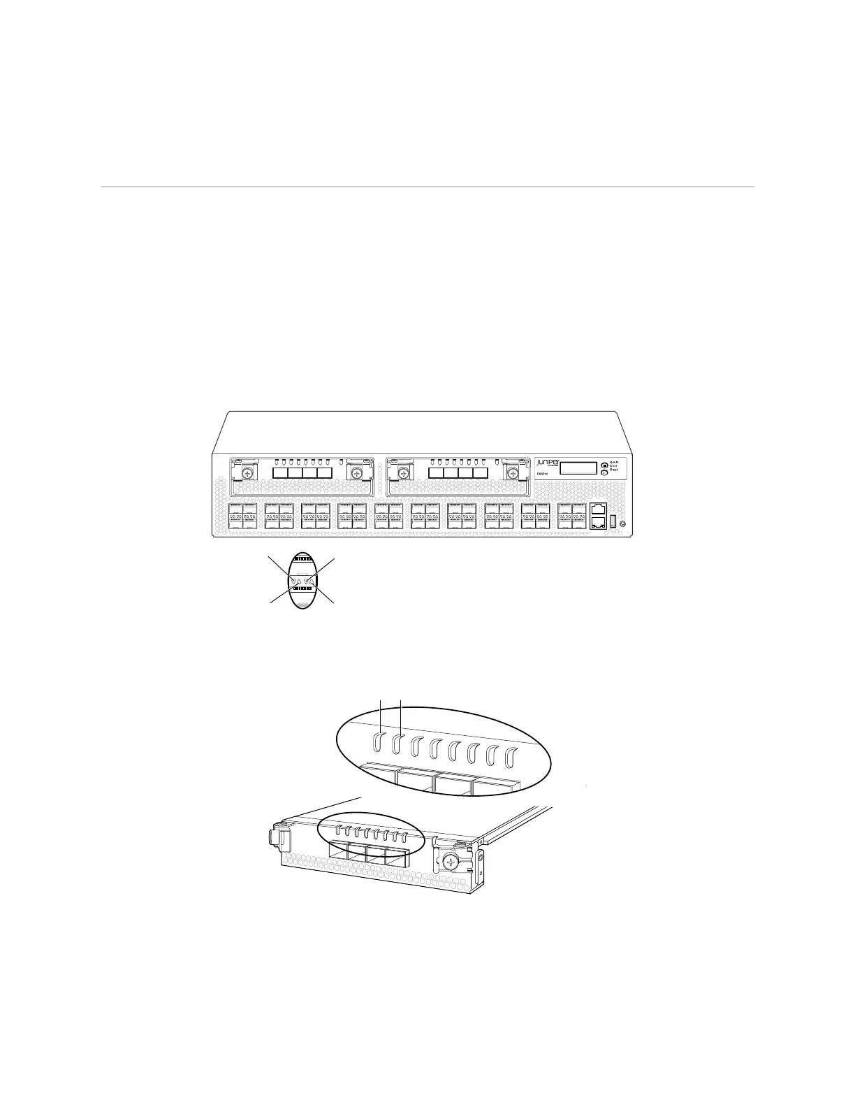
Network Port and Uplink Module Port LEDs in EX4500 Switches
Each network port and uplink module port on an EX4500 switch has two LEDs that
indicate link/activity and status. The figures in this topic show the location of these
LEDs:
■ Figure 7 on page 15 shows the location of the LEDs on the network ports on the
front panel of an EX4500 switch. The LEDs point toward the port to which the
LEDs belong.
■ Figure 8 on page 15 shows the location of the LEDs on the uplink module ports
on the SFP+ uplink module.
Figure 7: Network Port LEDs
g020802
0 2
1 3
0 21 3 ST 0 21 3 ST
4 6
5 7
8 10
9 11
12 14
13 15
16 18
17 19
20 22
21 23
24 26
25 27
28 30
29 31
32 34
33 35
36 38
CON
MGMT
37 39
Status
lower port
Status
upper port
Link/Activity
lower port
Link/Activity
upper port
Figure 8: Uplink Module Port LEDs
g020803
0
1
2
3
ST
Link/Activity
LED
Status
LED
0
1
2
3
The LEDs labeled Link/Activity LED in Figure 7 on page 15 and Figure 8 on page 15
indicate link activity.
Table 5 on page 16 describes the Link/Activity LED.
Network Port and Uplink Module Port LEDs in EX4500 Switches ■ 15
Chapter 2: Component Descriptions