You can check the status of fans and the chassis temperature from the Environment
Status option in the Status menu on the LCD panel. See “LCD Panel in EX4500
Switches” on page 9.
You cannot replace a single fan. If one or more fans fail, you must replace the entire
fan tray.
Related Topics ■ Installing a Fan Tray in an EX4500 Switch on page 75
■ Removing a Fan Tray from an EX4500 Switch on page 119
■ Field-Replaceable Units in EX4500 Switches on page 14
■ Rear Panel of an EX4500 Switch on page 8
■ Prevention of Electrostatic Discharge Damage on EX Series Switches on page 174
Uplink Modules in EX4500 Switches
EX4500 switches support SFP+ uplink modules. The SFP+ uplink module is a
hot-insertable and hot-removable field replaceable unit (FRU).
NOTE: Uplink modules and transceivers are not part of the EX4500 switch’s shipping
configuration. You must order them separately.
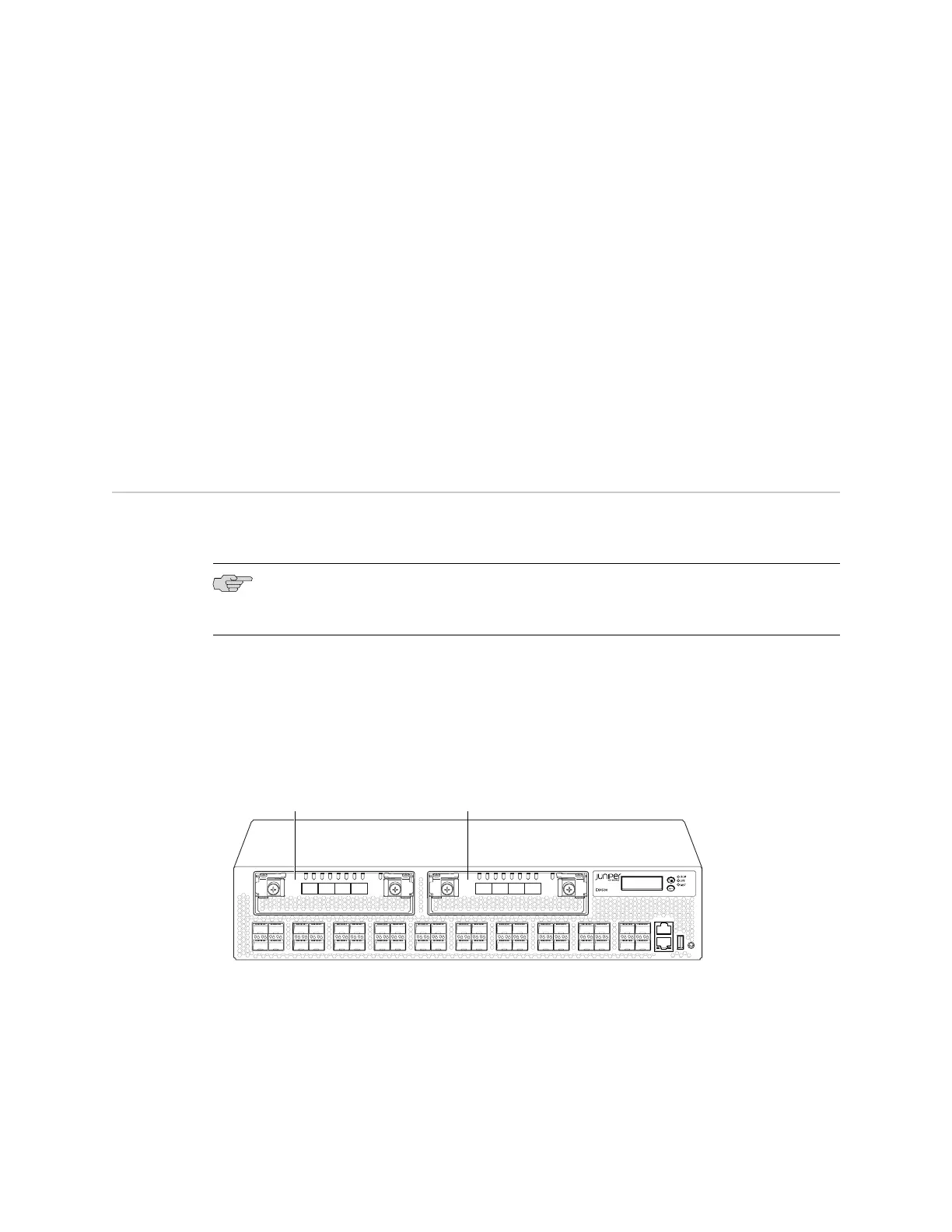
You can install up to two SFP+ uplink modules in an EX4500 switch. Both uplink
modules install horizontally on the front of the chassis. The uplink module slot on
the left is PIC 1. The uplink module slot on the right is PIC 2. See Figure 16 on
page 23.
Figure 16: Uplink Module Slots in an EX4500 Switch
g020856
0 2
1 3
0 1 2 3
ST ST
0 1 2 3
4 6
5 7
8 10
9 11
12 14
13 15
16 18
17 19
20 22
21 23
24 26
25 27
28 30
29 31
32 34
33 35
36 38
CON
MGMT
37 39
Uplink Module
(PIC 1)
Uplink Module
(PIC 2)
Each SFP+ uplink module provides four ports. Each module can house four 10-gigabit
small form-factor pluggable (SFP+) transceivers or four 1-gigabit small form-factor
pluggable (SFP) transceivers.
Uplink Modules in EX4500 Switches ■ 23
Chapter 2: Component Descriptions