Figure 11 on page 23 describes the connecons and components of the QFX5200-48Y management
panel.
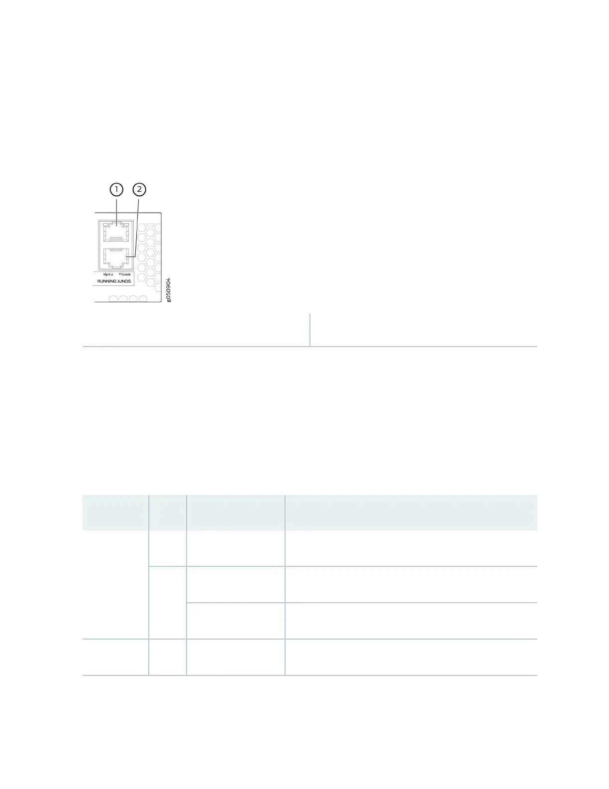
Figure 11: Management Panel Components on QFX5200-48Y
1—
em0–RJ-45 (1000 BASE-T) management
Ethernet port (Mgmt)
2—
RJ-45 console port (Console)
QFX5200-48Y Management Port LEDs
The management port and console port on a QFX5200-48Y have two LEDs that indicate link status and
link acvity. The management port is labeled Mgmt for 10/100/1000 BASE-T connecons. The le LED
indicates status; the right LED indicates link/acvity.
Table 11 on page 23 describes the management port LEDs.
Table 11: Management Port LEDs on a QFX5200-48Y Switch
LED Color State Descripon
Link/Acvity Unlit O No link is established, there is a fault, or the link is down.
Green On steadily A link is established, but there is no link acvity.
Blinking or ickering A link is established, and there is link acvity.
Status Unlit O The link is down.
23