SSG 5 Hardware Installation and Configuration Guide
10 Front Panel
Front Panel
This section describes the following elements on the front panel of an SSG 5 device:
System Status LEDs
Port Descriptions
System Status LEDs
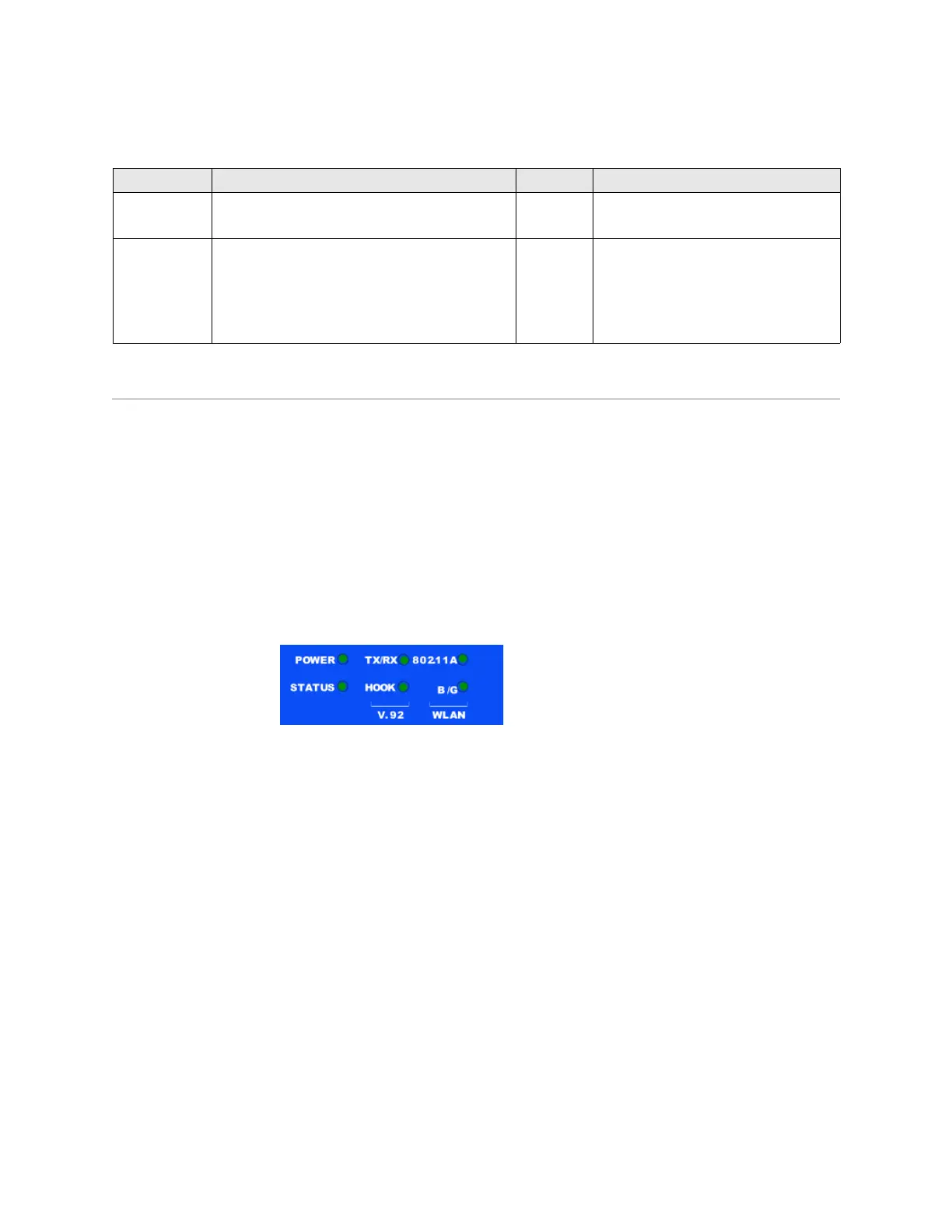
The system status LEDs display information about critical device functions. Figure 3
illustrates the position of each status LED on the front of the SSG 5 V.92-WLAN
device. The system LEDs differ depending on the version of the SSG 5 device.
Figure 3: Status LEDs
When the system powers up, the POWER LED changes from off to blinking green,
and the STATUS LED changes in the following sequence: red, green, blinking green.
Startup takes approximately two minutes to complete. If you want to turn the
system off and on again, we recommend you wait a few seconds between shutting
it down and powering it back up. Table 2 provides the type, name, color, status, and
description of each system status LED.
ISDN Enables the ISDN line to be used as the untrust or
backup interface. (S/T)
RJ-45 B-channels at 64 Kbps
Leased line at 128 Kbps
Antenna A & B
(SSG 5-WLAN)
Enables a direct connection to workstations in the
vicinity of a wireless radio connection.
RPSMA 802.11a (54 Mbps on 5GHz radio band)
802.11b (11 Mbps on 2.4 GHz radio band)
802.11g (54 Mbps on 2.4 GHz radio band)
802.11 superG (108 Mbps on 2.4 GHz and
5GHz radio bands)
Port Description Connector Speed/Protocol