Table 2 on page 13 describes the chassis status LEDs on SSR120, their colors and states, and the status
that they indicate.
Table 2: Chassis Status LEDs for SSR120
LED State and ColorStatus
LED 1—On, Blue
LED 2—Off, Unlit
LED 3—On, Blue
OS boot process is complete
LED 1—On, Amber
LED 2—Off, Unlit
LED 3—On, Blue
Device is powered off by the OS
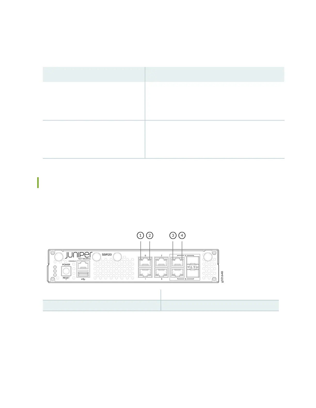
Network Port LEDs
Each network port has two LEDs to indicate the link activity and status of the port.
Figure 5: Network Port LEDs on SSR120
3—1— Link (RJ-45/SFP combo port)Link (Ethernet port)
4—2— Activity (RJ-45/SFP combo port)Activity (Ethernet port)
Table 3 on page 14 describes the Link and Activity LEDs on the network ports.
13