Page 62
Remote Control Unit
© JVA Technologies www.jva-fence.com JVA Z13 Manual
12.2 INSTALLATION
-
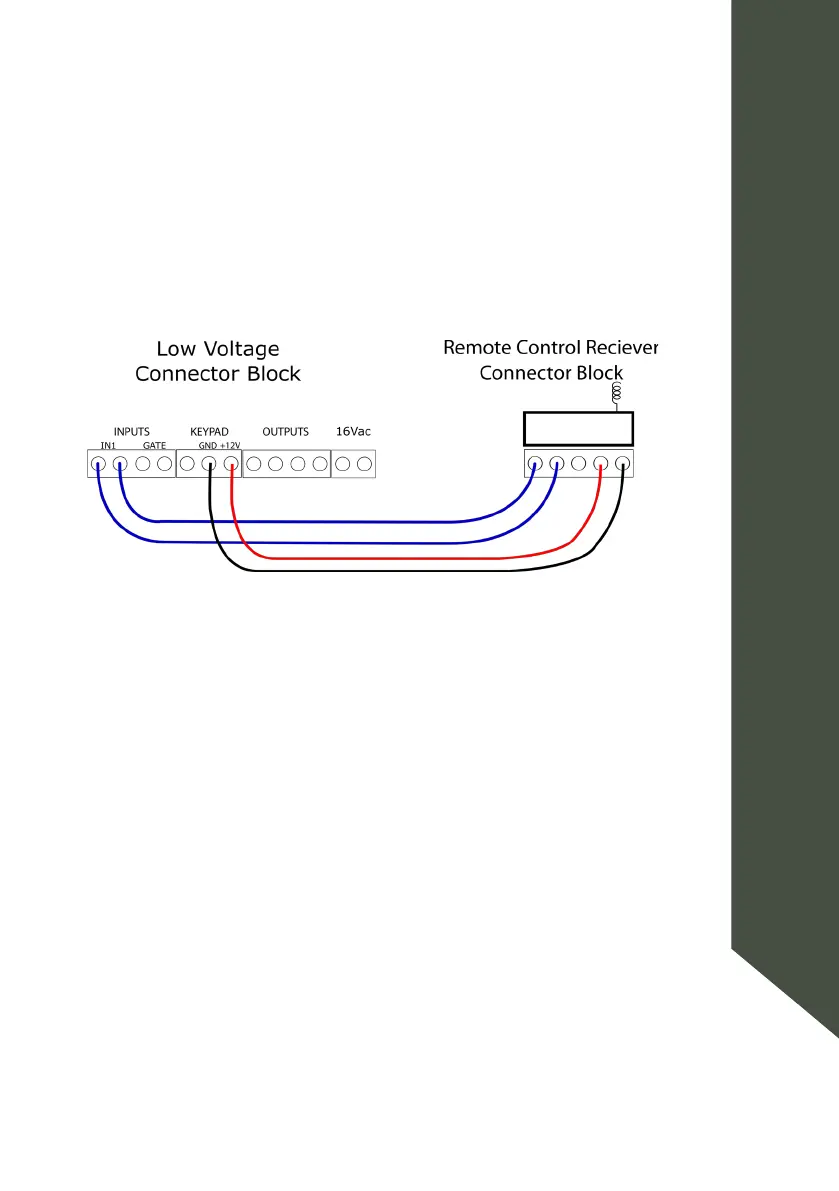
pad bus, and its output wired to IN1.
+12V and 0V (GND) from the KEYPAD terminals on the energizer to the
right-most terminals of the receiver, as per the diagram above.
Remote Control Receiver Wiring Diagram
12.3 OPERATION AND CONFIGURATION
Simply press the LOCK key to arm the energizer. Press the UNLOCK key to
disarm.
Should a remote control become lost or stolen, it is possible to disassoci-
remote controls from its memory.