28
VIDEO
LINE
IN
OUT
MONITOR
OUT
DC12V
DV
IN/OUT
IN OUT
OFF
AUDIO
REMOTE2
IN
B-YR-Y
SYNC IN
TIME CODE
IN OUT
Y
COMPONENT
OUT
CH 1/3 CH 2/4
IN
OUT
MONITOR
OUT
REMOTE1
TIMER
REC PLAY
SERIAL
REMOTE
SIGNAL
GND
Y/C
Y/C
Y/C
DV
DV
SYNC IN
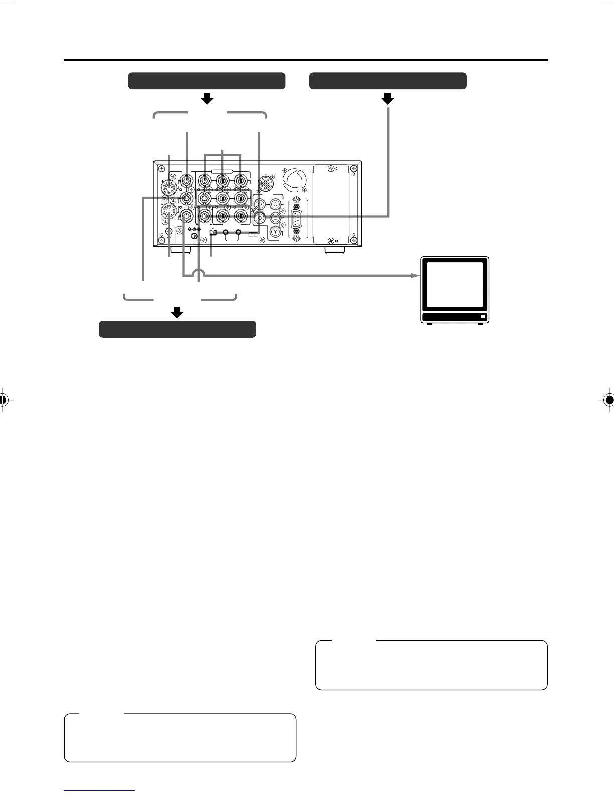
CONNECTION – Connecting video signals –
Video output, e.g., VCR Synchronization signal generator
Video output, e.g., VCR
Input
Composite
Component
BB signal
MONITOR OUT (Composite)
Monitor
Output
Composite
Component
Output signal
When BR-DV6000 enters the STOP, REC or
EDIT mode, the input signal (E-E image) is out-
put. In the PLAYBACK mode (including the play-
back of the pre-roll part during editing), play-
back images are output.
However, in the edit mode with analog input,
signals cannot be output to the DV OUT termi-
nal properly.
● Analog signal
• LINE OUT terminal (BNC): composite signal.
• Y/C OUT terminal (4-PIN): YC separate sig-
nal.
When a wide screen ID signal exists in the
video signal, the ID signal is output.
• COMPONENT OUT terminal (BNC3):
Component (Y/B-Y/R-Y) signals are output.
The output level is of ß cam (HIGH).
● Digital signal
•DV IN/OUT terminal: it outputs IEEE1394-
compliant digital video signals.
When a wide screen ID signal exists in the
video signal, the ID signal is output.
● Connection with a monitor TV
A monitor TV can be connected to the MONI-
TOR OUT terminal. Besides the composite
video signals, it also displays the on-screen dis-
play for status or menu screen.
Memo
Whether or not to enable SET UP for analog
I/O signals of signals can be selected with SET
UP in the VIDEO Menu screen (for NTSC only).
Memo
Set PB/DV IN in the SYSTEM (2/2) Menu
screen according to the signal format of the
tape to be played. (NTSC or PAL)
Input signal
The input video signal is selected with the IN-
PUT SELECT switch on the front panel. Set
VIDEO INPUT SEL in the VIDEO Menu screen
to select YC input or component input.
● Analog signal
• LINE IN terminal (BNC): composite signal
• Y/C IN terminal (4-PIN): YC separate signal
When a wide screen ID signal is being input,
the ID signal is recorded.
• COMPONENT IN terminal (BNC3):
The component (Y/B-Y/R-Y) signal.
The output level is of ß cam (HIGH).
● Digital signal
•DV IN/OUT terminal : IEEE1394-compliant
digital video signals
are input.
When a wide screen ID signal is being input,
the ID signal is recorded.
Set PB/DV IN in the SYSTEM (2/2) Menu
screen according to the signal format to be
input to the DV terminal. (NTSC or PAL).
DV6000U_28-051_Eng.p65e 06/03/03, 11:39 PM28