1-9
MX-GA77
Pull out the sound mode knob, volume knob, and
preset knob from the front side of front panel
assembly.
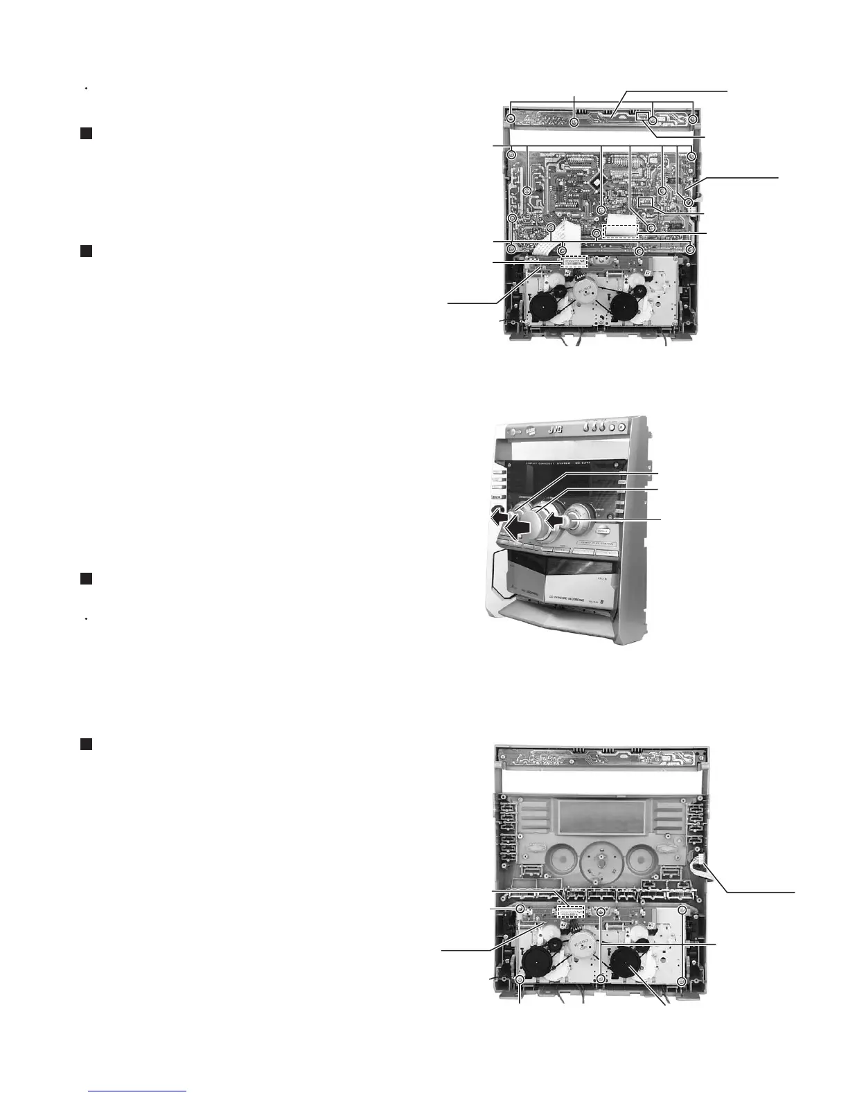
Disconnect the card wire from the connector UCW02
on the front board and the connector on the mecha.
board.
Remove the fourteen screws B attaching the front
board.
Disconnect the card wire from the connector UCW01
on the front board.
1.
2.
3.
4.
Removing the front board
(See Fig.1 and 2)
Disconnect the card wire from the connector UCW03
on the CD switch board.
Remove the four screws A attaching the CD switch
board.
1.
2.
Prior to performing the following procedure, remove
the front panel assembly.
Removing the CD switch board (See Fig.1)
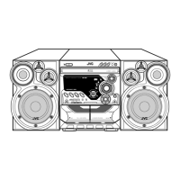
<Front panel assembly>
Prior to performing the following procedure remove
the front board.
You can pull out the headphone jack board.
1.
Removing the headphone jack board
(See Fig.3)
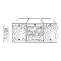
Disconnect the card wire from the connector on the
mecha. board.
Remove the six screws C attaching the cassette
mechanism assembly.
1.
2.
Removing the cassette mechanism
assembly (See Fig.3)
Fig.1
Fig.2
Fig.3
Headphone
jack board
Mecha.
board
Cassette mechanism
assembly
A
B
B
C
C
CD switch board
Front panel assembly (inner side)
Front panel assembly (inner side)
Front board
Sound mode knob
Volume knob
Preset knob
UCW03
Connector
UCW01
UCW02
C
(fixing the lug wire)
Mecha.
board
Connector