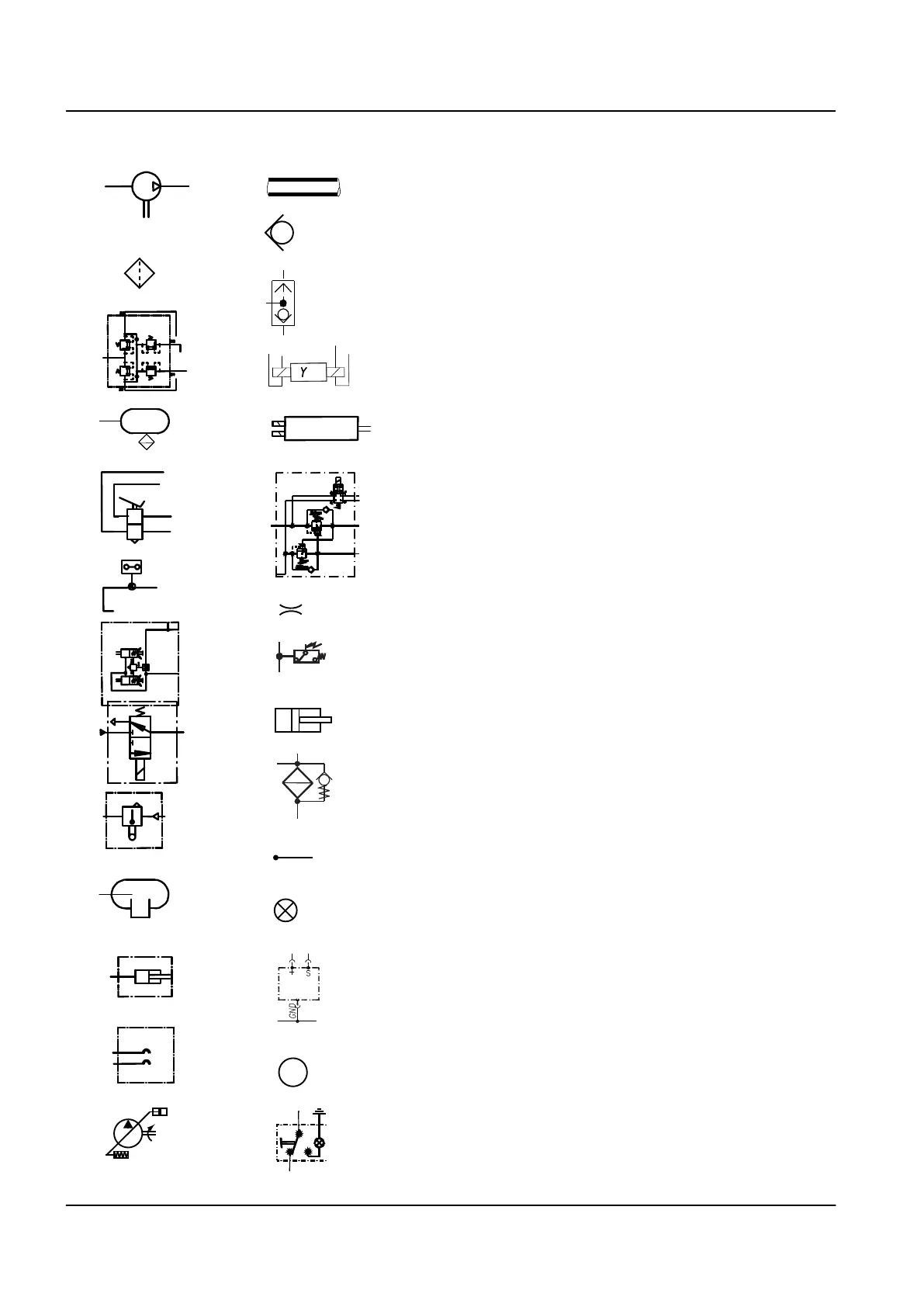
Explanation of the function description symbols
The following symbols are used in function descriptions. The sym‐
bols are based on standard symbols used in the electric and
hydraulic diagrams.
1.
Pneumatic air compressor
2.
Air filter
3.
Four-circuit protection valve in the pneumatic system
4.
Air tank
5.
Brake pedal valve in the pneumatic system
6.
Pressure switch in the pneumatic system
7.
Service brake and parking brake chamber in the pneumatic
system
8.
Solenoid valve in the pneumatic system
9.
Level valve in the pneumatic system
10.
Air spring in the pneumatic system
11.
Cylinder in the pneumatic system
12.
Palm type couplings in the pneumatic system
13.
Variable-displacement pump in the hydraulic system
14.
Pressure/return line in the hydraulic system
15.
Throttle valve in the hydraulic system
16.
Pressure-controlled shuttle valve in the hydraulic system
17.
Electrically controlled solenoid valve in the hydraulic system
18.
Electrically controlled directional valve in the hydraulic system
19.
Load control valve in the hydraulic system
20.
Throttle valve in the hydraulic system
21.
Pressure switch in the hydraulic system
22.
Cylinder in the hydraulic system
23.
Return filter in the hydraulic system
24.
Cable in the electric system
25.
Indicator light in the electric system
26.
Level sensor in the electric system
27.
Electric motor
28.
Control switch in the electric system
A
B
a
b
M
11
12
1
2
3
4
5
6
7
8
10
15
16
17
18
13
14
9
19
20
21
22
23
24
25
26
27
28
10 A Foreword – Reading this manual
TL2 Maintenance Manual
591 003 Default