3 Measure the belt tension in the center span of the pulleys.
An alternate method (deflection method) can be used to
check belt tension by applying 110 N (25 lbf) force between
the pulleys on v-belts. If the deflection is more than one belt
thickness per foot of pulley center distance, the belt tension
must be adjusted.
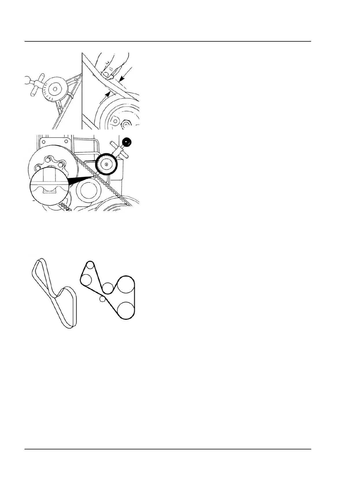
4 For cogged belts, make sure that the belt tension gauge is
positioned so that the center tensioning leg is placed directly
over the high point (hump) of a cog. Other positioning will
result in incorrect measurement.
Replace the cooling fan drive belt
General
Due to the number of drive belt arrangements, this procedure does
not cover all available cooling fan drive belt routing.
To make sure the cooling fan drive belt is routed correctly upon
installation, make a diagram of the cooling fan belt routing prior to
removing the belt as shown in the illustration.
A)
Crankshaft pulley/vibration damper
B)
Fan pulley
C)
Water pump pulley
D)
Refrigerant compressor pulley
E)
.Alternator pulley
F)
Tensioner idler pulley
NOTE
Some engine driven belts are installed/supplied by the vehicle's origi‐
nal equipment manufacturer (OEM). See the OEM service manual
for removal and installation instructions.
34 1 Engine – 1.7 Cooling system
TL2 Maintenance Manual
591 003 Default