KaControl for Door Air CurtainsINSTALLATION AND OPERATING INSTRUCTIONS
INSTALLATION AND OPERATING INSTRUCTIONS
1.96
46
Door air curtains
13. Functional Testing of Connected Assemblies
The KaController provides the option of checking the operation of the
connected external units independently of the software application.
The function of individual assemblies, such as the fan, can be directly
enabled and checked by means of entries on the KaController.
Hardware-related locks should be observed during the functional
test (refer to the respective wiring diagram!)
The functional checks of the connected assemblies are called up and
performed by the following operating steps:
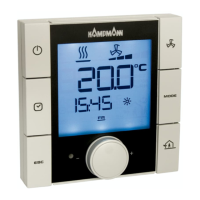
1. Switch off the door air curtain by:
• Pressing the ON/OFF key
or
• Pressing the navigator for a minimum of 5 seconds
or
• Turning the navigator to the left until OFF appears
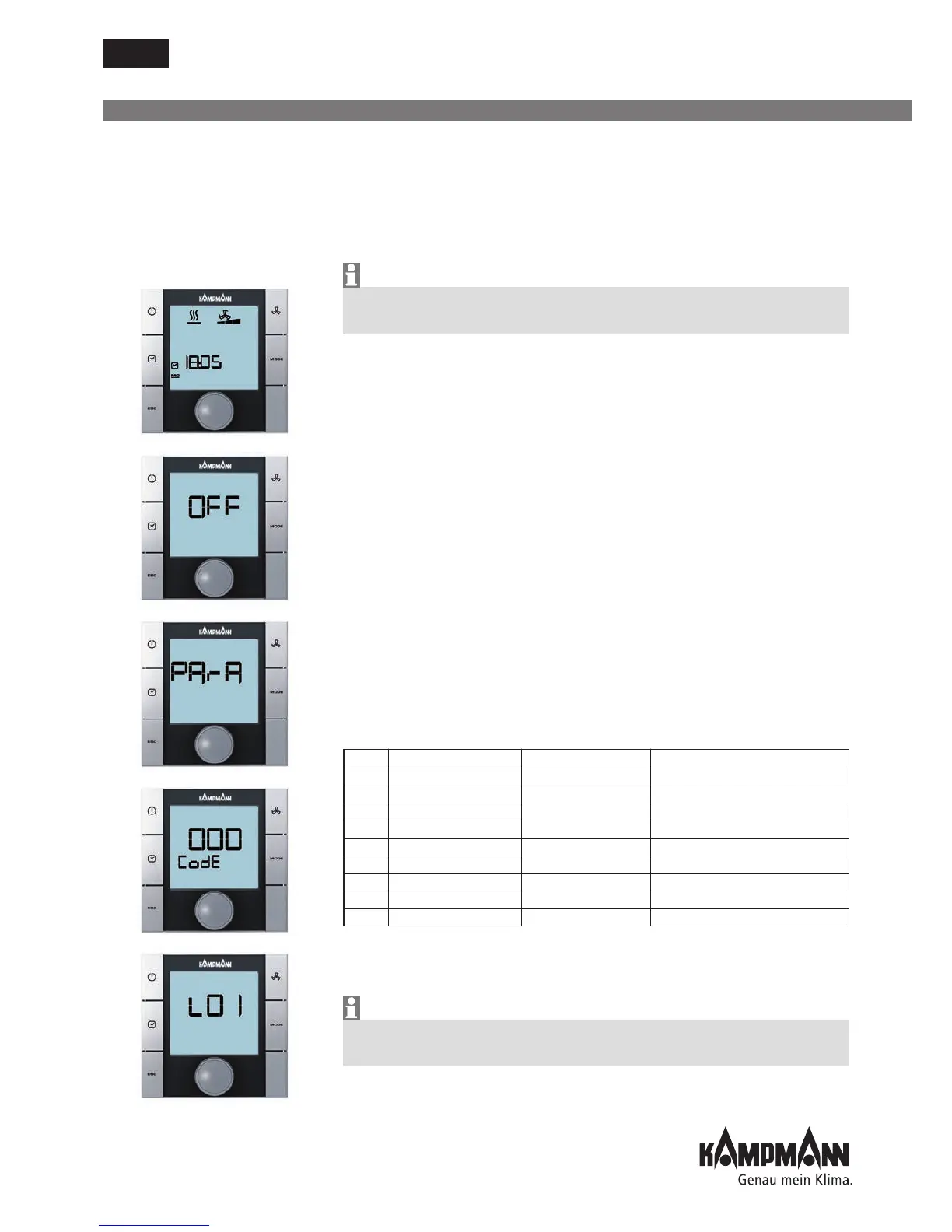
2. Call up the Parameter menu by pressing the navigator for a
minimum of 10 seconds. The display shows "Para" and then "CODE"
with the value 000 in sequence.
3. Select the password (Code) 77 by turning the navigator and confirm
by pressing the navigator.
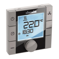
4. "L01" is shown on the display and the functional testing of the
connected assemblies can start.
Note:
The individual test steps are called up by pressing the navigator.
The default view with "OFF" on-screen display is shown once the test
(L08) has been completed.
Step Input Output Display flashes Display does not flash
L01* Input AI1 Sensor faulty Sensor ok
L02* Input AI2 Sensor faulty Sensor ok
L03* Input AI3 Sensor faulty Sensor ok
L04 Input DI1 Contact open Contact closed
L05 Input DI2 Contact open Contact closed
L06 Fan speed -- Increased actuation
0.0.10V Fan 0V --> 10V
L07 Valve output 1 -- Output V1 enabled
L08 Valve output 1 -- Output V1 enabled
* The control automatically detects the requisite sensors on the analog inputs
AI1-AI3 via the DIP switch settings. If sensors are defective or not connected,
this is shown by the respective display (L01-L03) flashing.
Note hardware-related locks during the functional test (refer to the
respective wiring diagram!)