6 3
KEB COMBIVERT F5
6
Name: Basis
16.04.02
Chapter Section Page Date
© KEB Antriebstechnik, 2002
All rights reserved
Functional Description Digital In- and Outputs
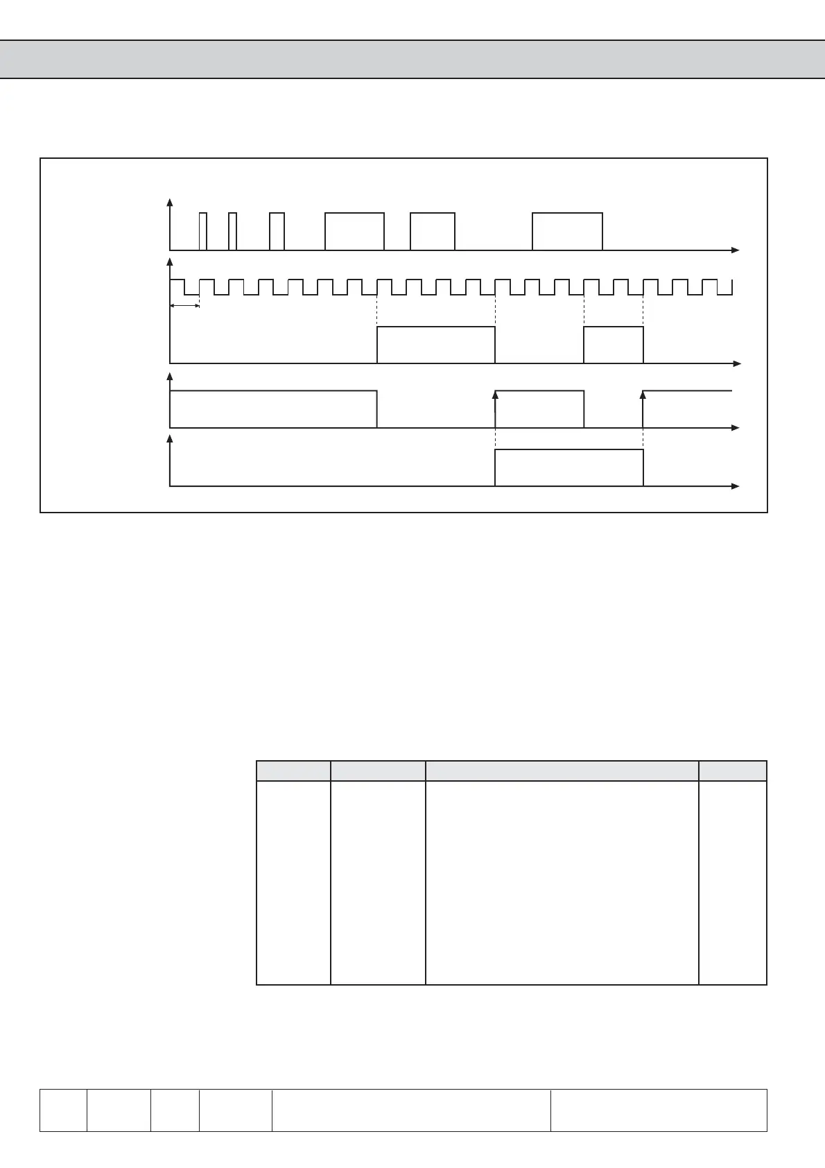
t1
t
t
t
t
1. 2. 1. 2. 1. 2. 1. 2.
Signal at
terminals
Scanning grid
(acceptance
at rising
edge)
Inverted signal
Input status at
edge-triggering
6.3.8 Strobe-
dependent Inputs
(di.6, di.7, di.8)
A Strobe signal is used mainly for triggering the input signals. For example, two inputs
shall be used for the parameter set selection. But the signals for the control do not
arrive exactly even, so for a short time it would be switched into an unintended set.
With active Strobe (scanning signal) the current input signals of the Strobe-dependent
inputs are accepted and kept until the next scanning.
With di.8 any input can be selected as Strobe-dependent input. With the control release
di.8 has no function since this is a static input.
With parameter di.6 the Strobe input is set. If several inputs are adjusted as Strobe
they are linked in OR-operation. At the next rising edge of the clock signal, the
Strobe signal is triggered.
di.8 Strobe-dependent inputs
di.6 Selection strobe signal
From where comes the Strobe
signal?
Which inputs are switched by
Strobe?
Fig. 6.3.7 Example of a signal flow diagram for input I1 (di.3=1; di.4=16; di.5=16)
Bit -No. Decimal value Function di.6 / di.8 / ru.22 / di.9 / di.10 Terminal
0 1 * ST (Prog. input „Control release/Reset“) X2A.16
1 2 RST (Prog. input „Reset“) X2A.17
2 4 F (Prog. input „Forward“) X2A.14
3 8 R (Prog. input „reverse“) X2A.15
4 16 I1 (Prog. input 1) X2A.10
5 32 I2 (Prog. input 2) X2A.11
6 64 I3 (Prog. input 3) X2A.12
7 128 I4 (Prog. input 4) X2A.13
8 256 IA (Internal input A) none
9 512 IB (Internal input B) none
10 1024 IC (Internal input C) none
11 2048 ID (Internal input D) none
* No function at di.8, as the control release works static.
t1: 1 ms at F5-General; 2 ms at F5-Basic