3
15
KEB COMBIVERT F5-G / B
Name: Basis
04.12.01
3
Section PageDate
© KEB Antriebstechnik, 2001
All Rights reserved
Chapter
HardwareControl Cards
3.1.3 Connection of
the control
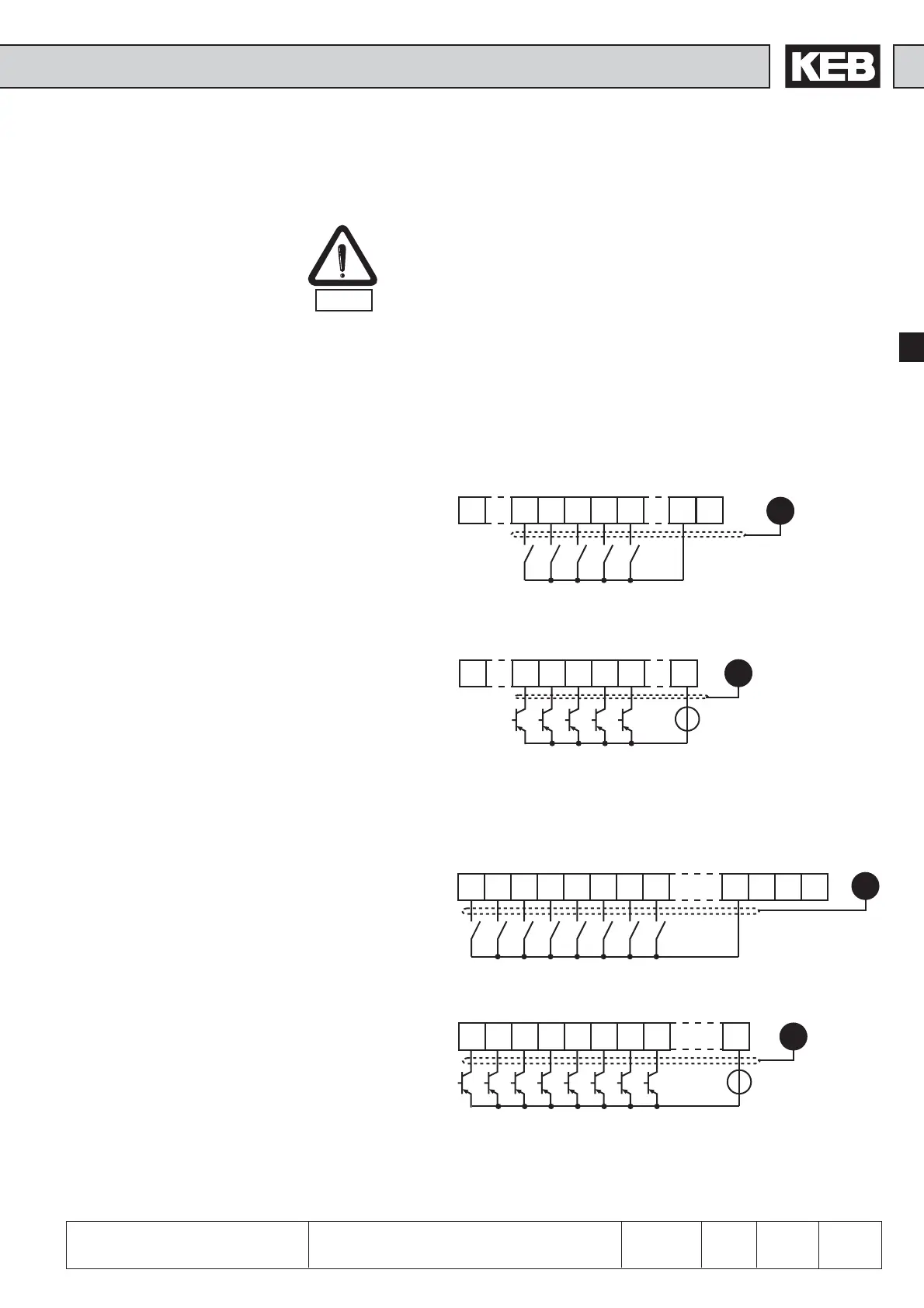
3.1.4 Digital inputs
In order to prevent a malfunction caused by interference voltage supply on the control
inputs, the following directions should be observed:
• Use shielded/drilled cables
• Lay shield on one side of the inverter onto earth potential
• Lay control and power cable separately (about 10...20 cm apart)
• Lay crossings in a right angle (in case it cannot be prevented)
EMC
Use of external voltage supply
Use of internal voltage supply
Control card BASIC:
Use of external voltage supply
Use of internal voltage supply
Control card GENERAL:
10 11 12 13 14 15
PE
X2A
16 17 20
21 22 23
10 11 12 13 14 15
PE
X2A
16 17 23
+
1 10 11 14 15
PE
16 20
22
X2A
1 10 11 14
PE
15 16 22
+
X2A
20...30 VDC
20...30 VDC
13...30V DC ±0%
smoothed
Ri = 2,1 kΩ
13...30V DC ±0%
smoothed
Ri = 2,1 kΩ