EasyManuals Logo

KEB COMBIVERT F5 Instructions For Use

KEB COMBIVERT F5
104 pages
To Next Page IconTo Next Page
To Previous Page IconTo Previous Page
Page #46 background imageLoading...
Page #46 background image
4 Mechanical Installation
4.1 Control cabinet installation
4.1.1 General instructions
To ensure the connection between master / slave systems, the distances between the
modules may not be exceeded => Mounting distances.
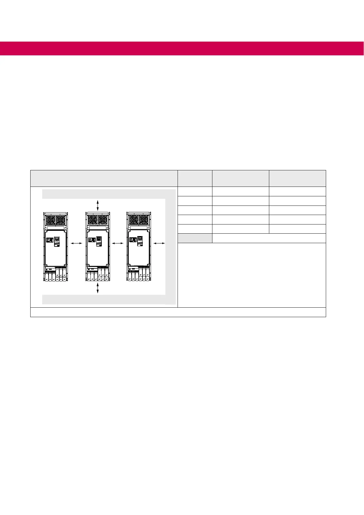
4.1.2 Mounting distances
Mounting distances Dimen-
sion
Distance in mm Distance in inch
C
A
B
DD
A 150 6
B 100 4
C 100 4
D
1)
50…230 2…9
X
2)
50 2
Cabinet wall
1)
Max. distance for master/slave systems is given by
the Sub-D connection between the modules.
2) Distance to preceding elements in the cabinet
door.
Figure 7: Mounting distances
46
MECHANICAL INSTALLATION

Table of Contents

Other manuals for KEB COMBIVERT F5

Questions and Answers:

Question and Answer IconNeed help?

Do you have a question about the KEB COMBIVERT F5 and is the answer not in the manual?

KEB COMBIVERT F5 Specifications

General IconGeneral
CategoryDC Drives
Enclosure RatingIP20
Control ModeVector Control, V/f Control
ProtectionOvercurrent, Overvoltage, Undervoltage, Overtemperature, Short circuit
Fieldbus CommunicationPROFIBUS, CANopen
Communication InterfacesRS-485
Input Voltage380-480V AC
Cooling MethodForced air cooling (fan)

Related product manuals