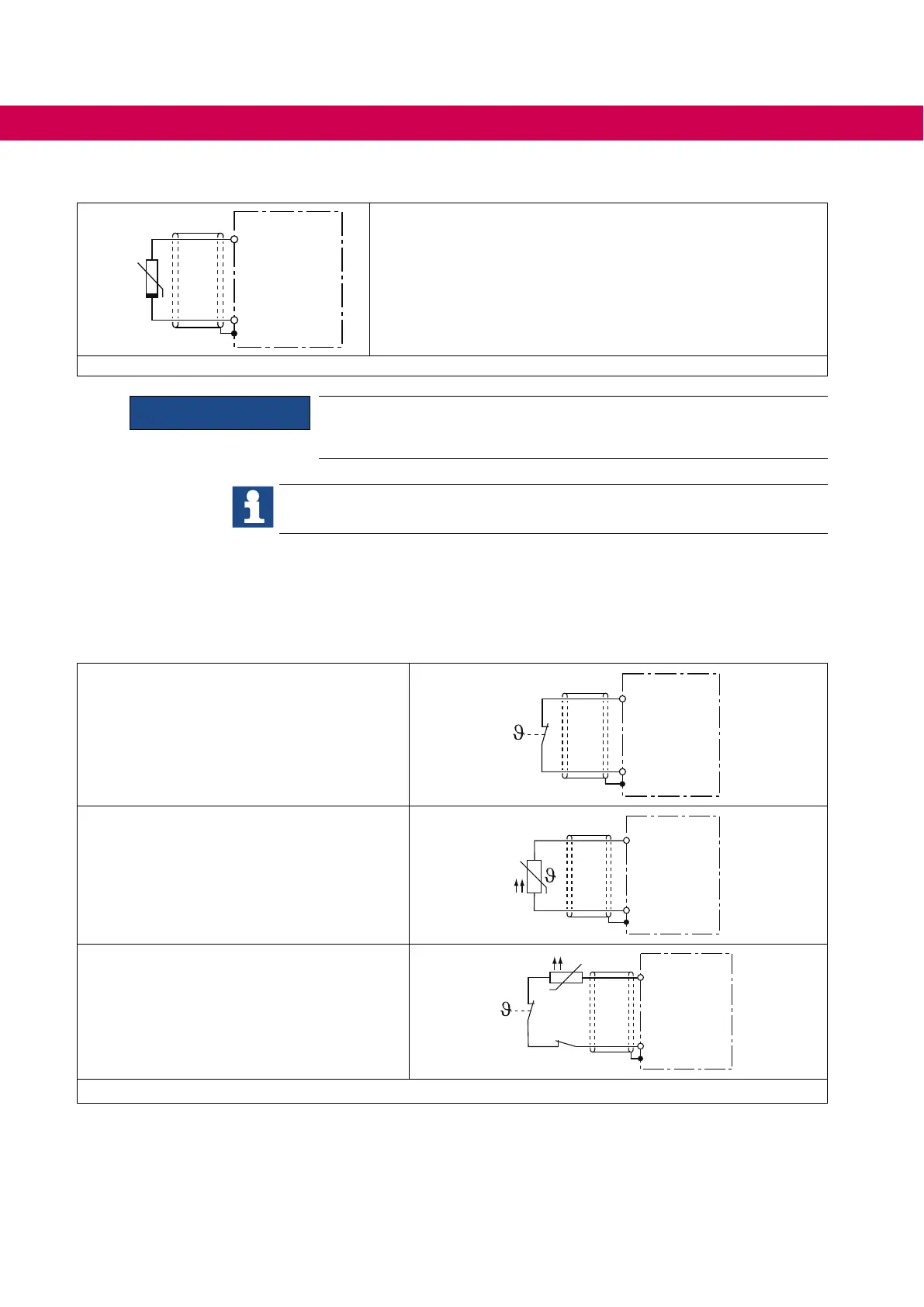
6.6.1 Use of the temperature input in KTY mode
T1
T2
+
KTY84
KTY sensors are poled semiconductors and must be operated in
forward direction! Connect anode to T1 ! Non-observance leads
incorrect measurement in the upper temperature range. Protec-
tion of the motor winding is no longer guaranteed.
Figure 21: Connection of a KTY sensor
ATTENTION
KTY sensors may not be combined with other devices. Otherwise
wrong measurements would be the consequence.
Examples for the construction and programming of a temperature control with
KTY84 evaluation can be taken from the F5 application manual.
6.6.2 Use of the temperature input in PTC mode
If the temperature input is operated in PTC mode, all possibilities are available for the
userwithinthespeciedresistancerange.Thiscanbe:
Thermal contact (NC contact)
T1
T2
Temperature sensor (PTC)
T1
T2
Mixed sensor chain
T1
T2
Figure 22: Wiring example in PTC mode
The function can be switched off with Pn.12 = “7“ (CP.28) if no evaluation of the input is
desired (standard in operating mode GENERAL). Alternatively a bridge can be installed
between T1 and T2.
74
ELECTRICAL INSTALLATION

 Loading...


