Page3.2 - 8 COMBIVERT R6-N © KEB, 2015-07
Operating and appliance data
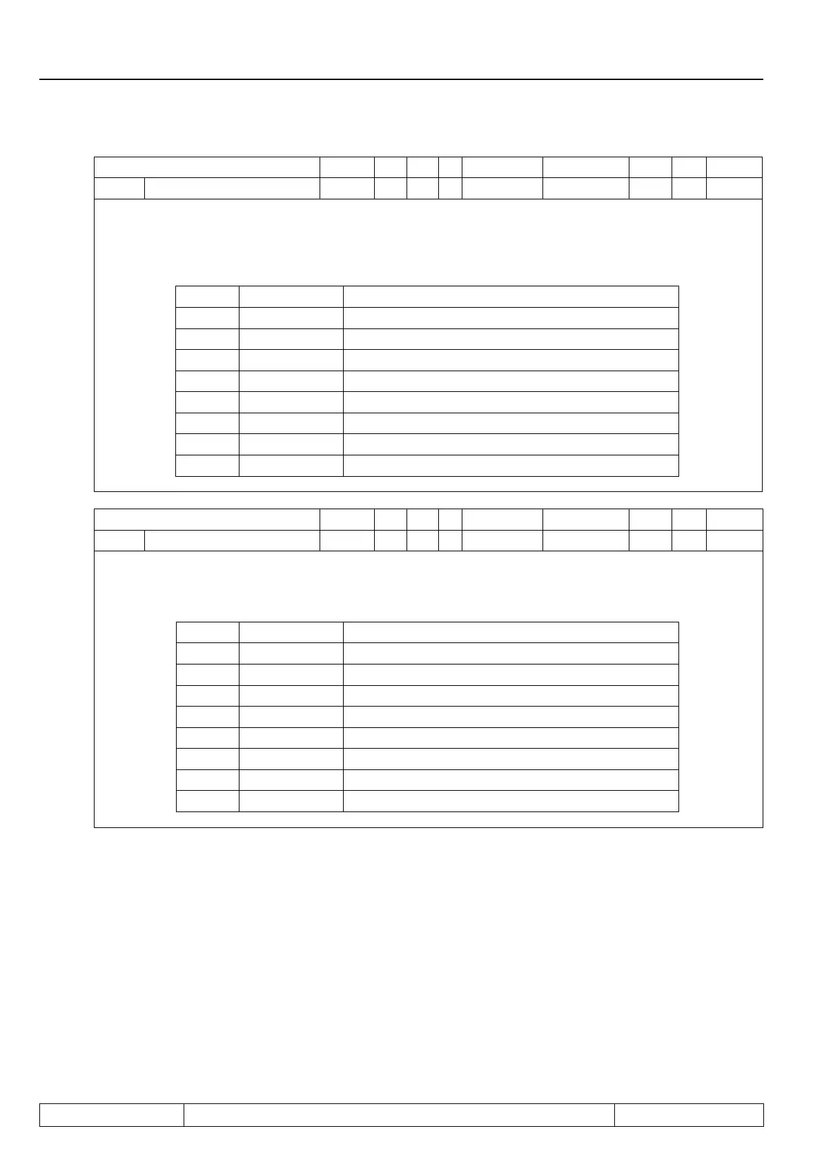
Parameter Addr. R PG E Min. value Max. value Res. [?] Default
ru.23 Output condition state 0217h ro - - 0 255 1 - -
With parameters do 00...do.07 switching conditions can be selected, that serve as base for setting the out-
puts. This parameter indicates which of the selected switching conditions are met before they are linked or
invertedbyprogrammablelogic(alsoseeChapt.7.3.„Digitaloutputs“).Accordingtofollowingtableaspecic
decimal value is given out for the switching conditions. If several of the selected switching conditions are met,
the sum of the decimal values is indicated.
Bit Decimal value Output
0 1 switching condition 0 (do.0)
1 2 Switching condition 1 (do.1)
2 4 Switching condition 2 (do.2)
3 8 Switching condition 3 (do.3)
4 16 Switching condition 4 (do.4)
5 32 Switching condition 5 (do.5)
6 64 Switching condition 6 (do.6)
7 128 Switching condition 7 (do.7)
Parameter Addr. R PG E Min. value Max. value Res. [?] Default
ru.24 Stateofoutputags 0218h ro - - 0 255 1 - -
Displayoftheoutputagsafterlogicstep1.Theselectedswitchingconditionsare linked inlogicstep1
(do.8...24)andindicatedhere(seechapt.7.3„Digitaloutputs“).Accordingtofollowingtableaspecicdec-
imalvalueisgivenoutforanyoutputags.Ifseveraloutputagsareset,thesumofthedecimalvaluesis
indicated.
Bit Decimal value Output
0 1 Flag 0
1 2 Flag 1
2 4 Flag 2
3 8 Flag 3
4 16 Flag 4
5 32 Flag 5
6 64 Flag 6
7 128 Flag 7
 Loading...
