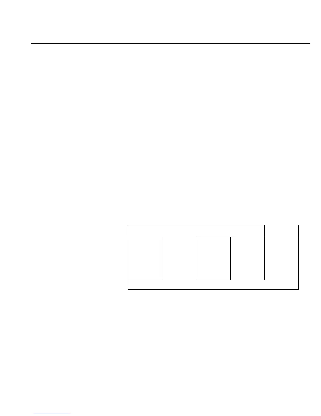
Test 301.1 — HI OHMS
Bank DC/OHM
Inputs Open
Expected Value 7 volts
Limits 0.7 volts
Fault Message 7V REFBOOT
Description
+7V is generated by buffering REFHI with op amp U139. This +7V,
which is used by the ohms circuit as a voltage reference, is switched by U133
(/7V control line low) to op amp U123 which is a unity gain buffer.
The +7V reference, now labeled REFBOOT, is routed through R272,
Q109 (/HIOHM control line low), the 9.9M
Ω
half of R117, Q101, Q102,
K101 (RESETK2 control line high), R304, Q104 (LOV control line high) to
U113. The unity gain output of U113 (BUFCOM) then goes to the A/D MUX
as in test 300.1 with a gain of
×
1. Measure +7V at AD_IN.
NOTE
K101 and K102 are latching relays. Any reference to their control line settings implies
that this setting, normally high (+5V), may be present for less than 100 milliseconds.
Remember this if attempting to troubleshoot these parts, especially when running the
BIT test in the MANUAL STEP mode.
Bit patterns
Bit pattern Register
QQ
87654321
—U106—
110v1111
QQ
87654321
—U109—
00101111
QQ
87654321
—U134—
1v10001v
—U130—
10111101
QQ
87654321
—U121—
10000100
ACDC_STB
MUX_STB
IC pins: Q8=11, Q7=12, Q6=13, Q5=14, Q4=7, Q3=6, Q2=5, Q1=4
Troubleshooting 2-33