Performance Verification
1-11
Follow the steps below to verify ACI measurement accuracy.
CAUTION
Do not apply more than 2A, 250V to the
AMPS input, or the current protection
fuse will blow.
1. Turn on the Model 2001 and the calibrator, and allow a
one-hour warm-up period before making measure-
ments.
2. Connect the Model 2001 to the calibrator, as shown in
Figure 1-5. Be sure to connect calibrator HI to the
AMPS input, and connect calibrator LO to INPUT LO
as shown.
3. Restore Model 2001 factory default conditions, as ex-
plained in paragraph 1.7.
4. Select the AC current function and the 200µA range on
the Model 2001.
5. Set the calibrator output to 190.000µA AC at a frequen-
cy of 40Hz, and allow the reading to settle.
6. Verify that the Model 2001 reading is within the limits
for the present current and frequency summarized in Ta-
ble 1-7.
7. Repeat steps 4 and 5 for each frequency listed in Table
1-7.
8. Repeat steps 4 through 7 for the remaining ranges and
frequencies listed in Table 1-7.
1.8.4 AC current verification
AC current verification is performed by applying accurate
AC currents at specific frequencies and then verifying that
Model 2001 readings fall within specified limits.
Table 1-6
Limits for DC current verification
2001 DCI
range
Applied DC
current
Reading limits
(1 year, 18° to 28°C)
200µA
2mA
20mA
200mA
2A
190.0000µA
1.900000mA
19.00000mA
190.0000mA
1.900000A
189.9000µA
to
190.1000µA
1.899200mA
to
1.900800mA
18.99200mA
to
19.00800mA
189.9010mA
to
190.0990mA
1.898200A
to
1.901800A
NOTES:
1. Repeat procedure for negative currents.
2. Reading limits shown do not include calibrator uncertainty.
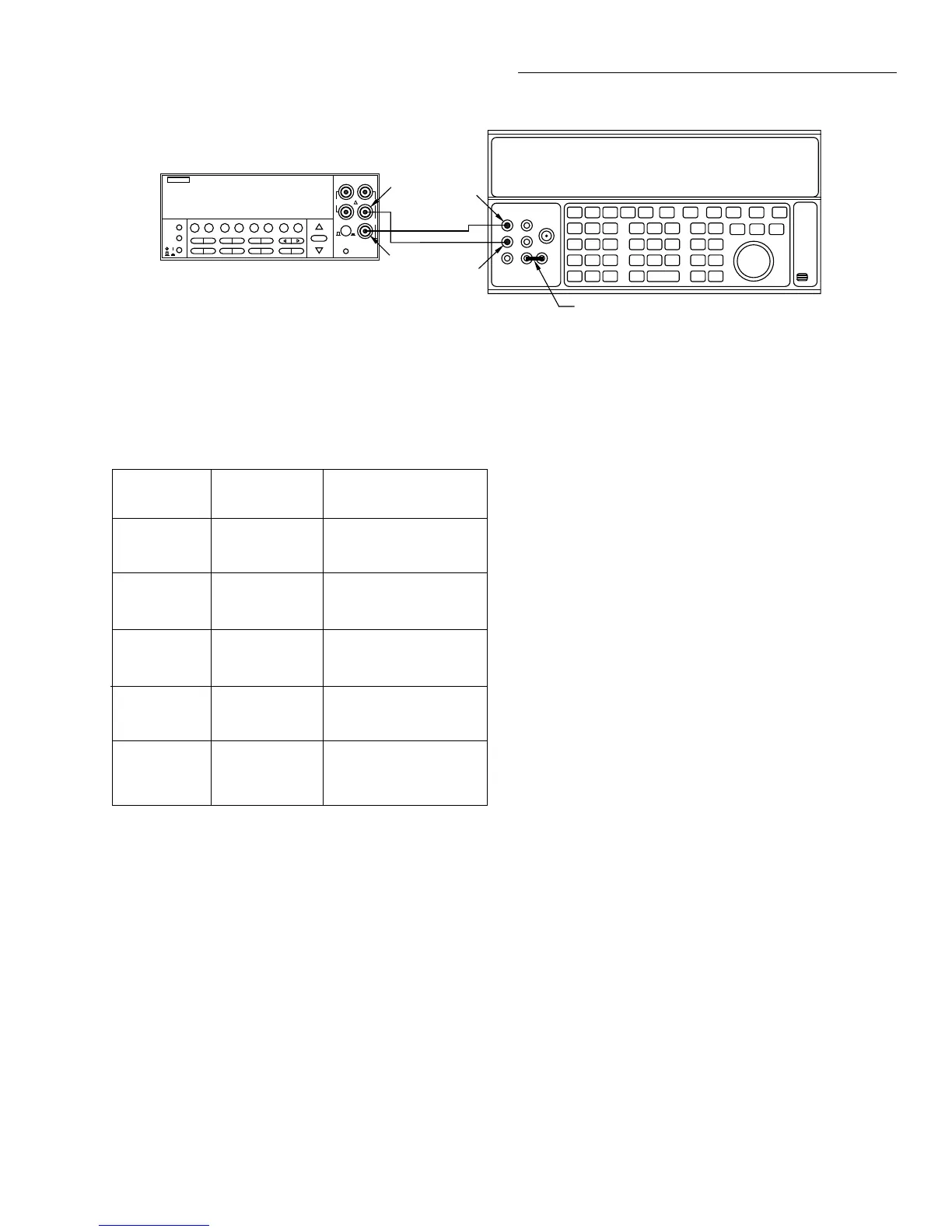
Figure 1-4
Connections for DC current verification
NEXT
DISPLAY
PREV
POWER
DCV ACV DCI ACI Ω2 Ω4
FREQ TEMP
REL TRIG STORE RECALL
INFO LOCAL CHAN SCAN CONFIG MENU EXIT ENTER
RANGE
AUTO
FILTER MATH
RANGE
2001 MULTIMETER
SENSE
Ω 4 WIRE
HI
INPUT
LO
INPUTS
CAL
500V
PEAK
F
R
FRONT/REAR
2A 250V
AMPS
350V
PEAK
1100V
PEAK
19.00000 mADC
Output HI
Input
LO
Output
LO
Model 2001
5700A Calibrator (Output DC Current)
Amps
Ground link installed.
Note: Use internal Guard (EX GRD LED is off).
 Loading...


