Troubleshooting
2-6
2.9 Principles of operation
The following information is provided to support the trou-
bleshooting tests and procedures previously covered in this
section of the manual. Most circuits in the Model 2002 are
tested and/or exercised by Built-in Test, which is described
in detail in paragraphs 2.10 and 2.11. Since the display board
and the power supply are not tested by Built-in Test, some
basic theory is provided for these circuits in paragraphs 2.9.2
and 2.9.3.
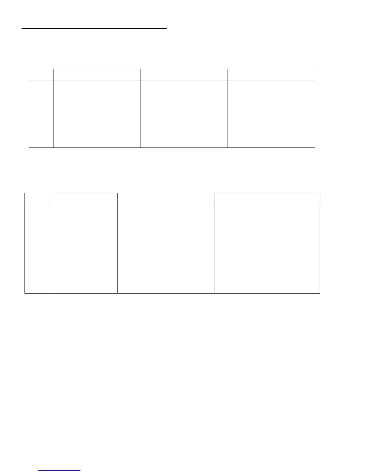
Table 2-5
Display board checks
Step Item/component Required conditions Remarks
1
2
3
4
5
6
7
FRONT PANEL TESTS
P1033, pin 5
CR902 cathode
P1033, pin 12
U902, pin 43
P1033, pin 8
P1033, pin 10
Verify that all pixels operate
+5V, ±5%
+60V, ±10%
Goes low briefly on power-up,
then goes high
4MHz square wave
Pulse train every 1msec
Brief pulse train when front panel
key pressed.
Use SELF-TEST MENU selection
Digital +5V supply
VFD +60V supply
Microcontroller RESET line
Controller 4MHz clock
Control from main processor
Key down data sent to main pro-
cessor.
Table 2-6
Display board checks
Step Item/component Required conditions Remarks
1
2
3
4
5
6
7
8
9
10
11
12
F101 line fuse
Line power
U108, pin 3
U110, pin 3
U109, pin 3
U107, pin 3
CR114, +BS
CR115, -BS
U105, pin 3
U105, pin 2
U619, +5VC
U629, pin 3
Check continuity
Plugged into live receptacle, power on
+5V, ±5%
+5V, ±5%
+15V, ±0.75V
-15V, ±0.75V
+34V to +38V
-34V to -38V
≈+18V
+8V
+5V, ±5%
+5V, ±5%
Remove to check
Check for correct power-up sequence
Referenced to Common 3
Referenced to digital common
Referenced to COM
Referenced to COM
Referenced to Common 3
Referenced to Common 3
Referenced to Isolated Common
Referenced to Isolated Common
Referenced to Digital Common
Referenced to Digital Common
2.9.1 Block diagrams
Figure 2-1 provides an overall block diagram of the Model
2002, while Figures 2-2 through 2-5 show block diagrams of
the power supply, display board, digital board, and analog
board respectively.

 Loading...


