Routine Maintenance
1-3
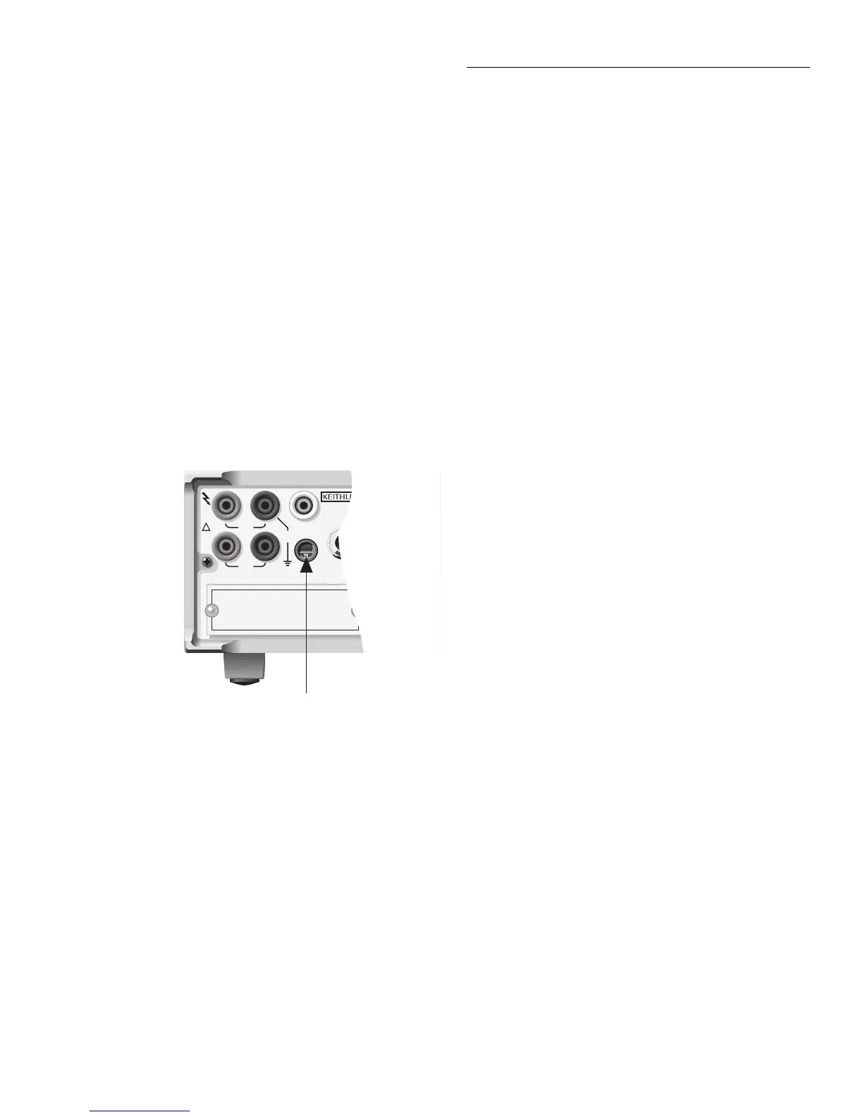
1.3.2 Rear AMPS input fuse
The rear AMPS input fuse is located just below the AMPS in-
put jack (see Figure 1-3). Perform the following steps to re-
place the fuse:
1. Insert a bladed screwdriver into the slot of the fuse car-
rier.
2. While pushing in, turn the screwdriver counter-clock-
wise until the spring loaded fuse carrier releases from
the fuse holder.
3. Pull out the fuse carrier and replace the fuse with the
type specified in Table 1-2.
CAUTION
To prevent instrument damage, use only
the fuse type specified in Table 1-2.
4. Re-install the fuse carrier.
1.4 Fan filter cleaning
The filter for the cooling fan requires periodic cleaning to
maintain proper ventilation. The fan filter is accessible from
the rear panel. Perform the following steps to remove the fil-
ter for cleaning:
1. While facing the rear panel, locate the lower right-hand
corner of the filter cover plate.
2. At this corner, place a thin-bladed screwdriver between
the cover plate and the rear panel, and gently pry the fil-
ter assembly away from the chassis.
The filter element is permanently fixed to the cover plate. Do
not attempt to remove the filter element from the cover plate.
WARNING
Exercise care when handling the filter
assembly. The filter element is a metal
screen with sharp edges that could cause
injury if not handled carefully.
The filter element is made of a rugged metal screen allowing
the use of any type cleaning solution to clean it. A small met-
al brush can be used to remove dirt and debris. After cleaning
the filter, rinse thoroughly with water. Make sure the filter as-
sembly is completely dry before re-installing it.
1.5 Firmware updates
It is possible that you may receive a firmware update from
Keithley to enhance operation and/or fix “bugs”. The firm-
ware for the main microprocessor is contained in two
EPROMS installed in sockets on the PC board to make re-
placement relatively easy.
The replacement procedure requires that the case cover be
removed, and these static-sensitive devices require special
handling. As a result, the firmware update procedure should
be performed only by qualified service personnel. The proce-
dure to replace the firmware EPROMS is contained in para-
graph 3.8.
Figure 1-3
Rear AMPS input fuse location
Amps
Fuse
WARNING:NO INTERNAL OPERATOR SERVICABLE PARTS,SERVI
WARNING:NO INTERNAL OPERATOR SERVICABLE PARTS,SERVI
CAUTION:FOR CONTINUED PROTECTION AGAINST FIRE HAZARD,REPLA
CAUTION:FOR CONTINUED PROTECTION AGAINST FIRE HAZARD,REPLA
EXTERNAL
TRIGGER
INPUT
INPUT
1100V
PEAK
350V
PEAK
500V
PEAK
AMPS
2A MAX
AMPS
FUSE
2A, 250V
SENSE
Ω 4 WIRE
HI LO
!
OPTION SLOT

 Loading...


