Troubleshooting
2-27
2.11.6 Integration tests
The 202 Integration series of tests check the selectable integration times of the ASIC U816. This
test is accomplished by loading the shift registers U809 and U810 with data words that will se-
lect the I15 through I0 inputs to U816 one at a time. The I15 through I0 inputs to U816 control
the length of the integration time. The exception is that the I0 input will always be set high due
to internal component requirements. A zero level is applied to the A/D and integrated for each
integration time for a baseline value. Zero baseline values are acquired during the odd-numbered
tests, and the values are used for a comparison in the even-number tests. The 7V reference is
applied to the A/D and integrated for each integration time during the even-numbered tests. The
7V reference is compared to the zero, and the result is a number of counts that is relative to the
length of the integration time. Each test will have an integration time that is smaller due to se-
lecting a lower order I, and the counts will then be a division of the first value acquired. The cir-
cuit setup for zero and 7V reference will be in tests 202.1 and 202.2. The remaining tests will
refer to the first two tests. HIGH and LOW logic levels refer to +5V and 0V respectively.
Test 202.1 — Baseline for test 202.2
Type
Circuit Exercise
Fault message None
Description Integration time is set up with I15 and I0 high (longest integration time), all other I lines low.
U222 is set up to switch common through R259 and S1 pin 4 input to the A/D buffer U226. U226
is set up for X1 gain through U227 pin 2 to 3 with /X1 pin 1 low. Also, common is switched
through R312 and U242 pins 2 to 3, through R311 and to pin 3 of U253. U253 is the buffer for
ADGND. ADGND is routed to A/D_IN through the parallel combination of R285 and R286.
Common is the input to A/D_IN. A zero reading is acquired and stored as baseline value for test
202.2.
Drawing reference Analog Board; 2002-100
A/D Converter; 2002-160
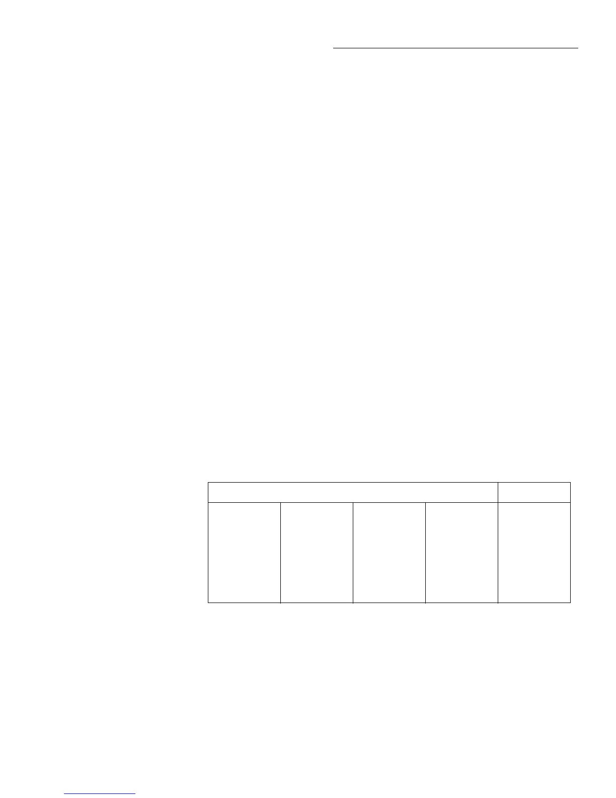
Bit patterns
Bit pattern* Register
—U400—
01111011
—U811—
00001101
—U224—
00010111
—U432—
10000000
—U810—
10000000
—U206—
01110000
—U203—
10001110
—U411—
11111011
—U809—
00000001
—U207—
00001111
—U221—
11101001
—U406—
00000100
AD_STB
MUX_STB
R1_STB
R2_STB
*Bits associated with register IC terminals as follows:
QQQQQQQQ
87654321 87654321 87654321 87654321
IC pins: Q8=11, Q7=12, Q6=13, Q5=14, Q4=7, Q3=6, Q2=5, Q1=4.
 Loading...


