Troubleshooting
2-26
Bit patterns
Test 201.3 — 1.75 Volt Reference
Type
Pass/Fail
Fault message Cannot measure 1.75V at A/D
Description The 7V reference REFHI generated by U219 and associated circuitry is connected to buffer
U254. The output of U254 is connected to U230. The 7V reference is switched at 600Hz through
U230. U235 and buffer U241 along with the 25% duty cycle of the 600Hz clock signal, generate
the 1.75 volt reference (2VREF). 2VREF is switched through R260 and U222 pin 6 to U226.
U226 is set up for X1 gain through U227 pin 2 to 3 with /X1 pin 1 low. REFLO is switched
through R310 and U242 pins 7 to 6, through R311, and to pin 3 of U253. U253 is the buffer for
ADGND. ADGND buffer with REFLO signal is connected to the bottom of the parallel combi-
nation of R285 and R286. A/D_IN will be the difference voltage of 2VREF and REFLO
(ADGND). The A/D is triggered and the 2VREF reading in counts is acquired. A calculation is
made with the values stored in 201.1, 201.2 to determine the proper operation and linearity of
the A/D converter.
Drawing reference Analog Board; 2002-100
Components Reference circuit, the A/D converter, or the signal paths routing the values to components the A/D.
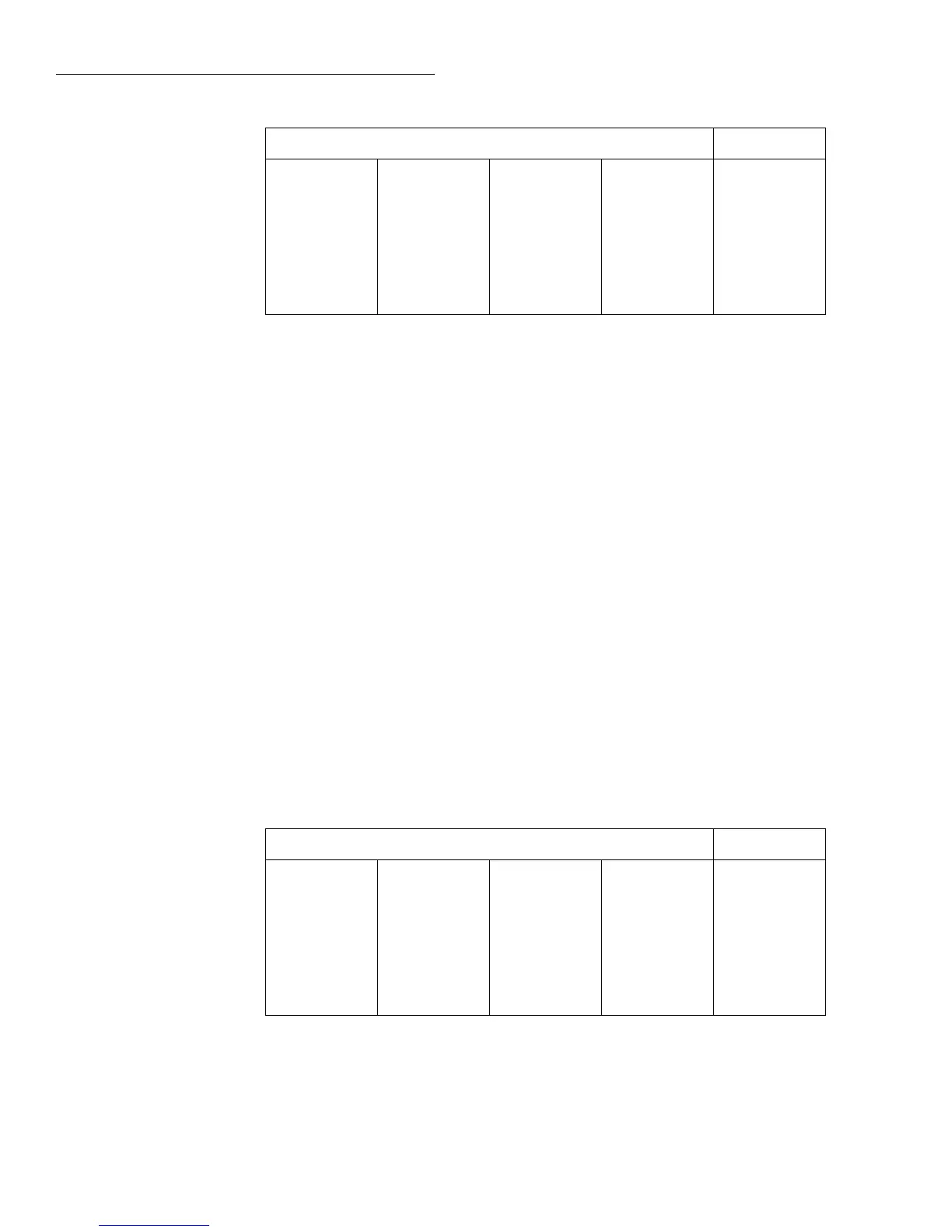
Bit patterns
Bit pattern* Register
—U400—
01111011
—U811—
00001101
—U224—
00010111
—U432—
10000000
—U810—
00010111
—U206—
01110000
—U203—
10001110
—U411—
11111011
—U809—
01101111
—U207—
00110111
—U221—
11101001
—U406—
00000100
AD_STB
MUX_STB
R1_STB
R2_STB
*Bits associated with register IC terminals as follows:
QQQQQQQQ
87654321 87654321 87654321 87654321
IC pins: Q8=11, Q7=12, Q6=13, Q5=14, Q4=7, Q3=6, Q2=5, Q1=4.
Bit pattern* Register
—U400—
01111011
—U811—
00001101
—U224—
00010111
—U432—
10000000
—U810—
00010111
—U206—
01110000
—U203—
10001110
—U411—
11111011
—U809—
01101111
—U207—
01010111
—U221—
11101001
—U406—
00000100
AD_STB
MUX_STB
R1_STB
R2_STB
*Bits associated with register IC terminals as follows:
QQQQQQQQ
87654321 87654321 87654321 87654321
IC pins: Q8=11, Q7=12, Q6=13, Q5=14, Q4=7, Q3=6, Q2=5, Q1=4.

 Loading...


