Front Panel Operation
2-122
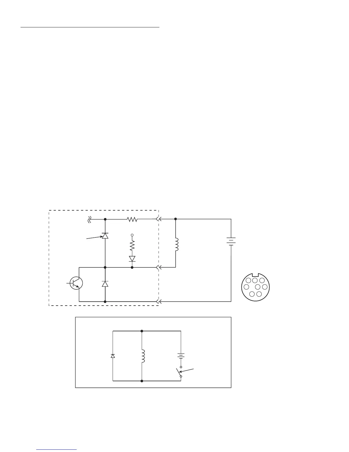
An externally powered relay connected to the digital output
port is shown in Figure 2-81. Other externally powered de-
vices can be similarly connected by replacing the relay with
the device. When using the Model 6517A’s collector outputs
to turn on externally powered devices, set the corresponding
digital output line parameters as follows (set through the
GENERAL/DIGITAL I/O menus):
STATE=ON
LOGIC-SENSE=ACTIVE-LOW
In the low state (0V), the output transistor sinks current
through the external device. In the high state, the output tran-
sistor is off (transistor switch is open). This interrupts current
flow through the external device. Most applications use ac-
tive-low (ON=0V) LOGIC-SENSE. Use the LOGIC-
SENSE menu to check or change the sense of each digital
output lines (refer to the LOGIC-SENSE section of this para-
graph).
Outputs used as logic inputs
To use the digital outputs as logic inputs to active TTL, Low-
power TTL, or CMOS inputs:
1. Connect the Model 6517A digital outputs to the logic in-
puts.
2. Connect the digital grounds.
3. Using the STATE menu, check output state setting of the
Model 6517A output lines. The STATE value for each
output used should be ON.
4. Using the LOGIC-SENSE menu, check the logic-sense
setting of the Model 6517A output lines (TTL1 through
TTL4). Make sure the correct LOGIC-SENSE value is
selected for each output line. The LOGIC-SENSE value
varies according to the type of TTL, Low-power TTL, or
CMOS inputs used (ACTIVE-HIGH or ACTIVE-LOW).
When low (0V), the output sink can drive at least 10 standard
TTL inputs. When high (+5V), the 10kΩ pull-up resistor will
source >100µA while remaining at a >3.75V output (a reli-
able logic high).
(+)
(-)
To Other Three
Digital Outputs
10Ω
Pin 3 - External Voltage Flyback
Connection (+5V to +30V)
+5V
10kΩ
Pull Up
Resistor
Pin 4 -Digital Output #1
Pin 8 -Digital Ground
Digital Output #1
Flyback Diode
1
2
3
4
5
6
7
8
DIGITAL
OUT
(Connector J1015)
Model 6517
External Power
(+5V to +30V)
Relay Coil
External Power
(+5V to +30V)
Relay
Coil
Equivalent Circuit
Flyback
Diode
Transistor
Switch
(+)
(-)
igure 2-81
Sample externally powered relays