Front Panel Operation
2-30
Source capacitance
DUT source capacitance will also affect the noise perfor-
mance of the Model 6517A ammeter. In general, as source
capacitance increases, the noise also increases. To see how
changes in source capacitance can affect noise gain, let us
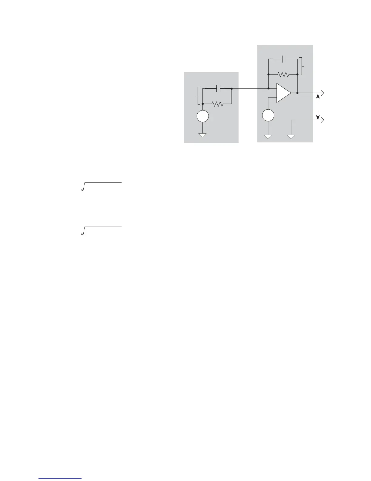
again refer to the simplified ammeter model in Figure 2-28.
The elements of interest for this discussion are the source ca-
pacitance, C
S
and the feedback capacitance C
F
. Taking into
account the capacitive reactance of these two elements, our
previous noise gain formula must be modified as follows:
Here, Z
F
represents the feedback impedance made up of C
F
and R
F
, while Z
S
is the source impedance formed by R
S
and
C
S
. Furthermore,
and,
Note that as C
S
increases in value, Z
S
decreases in value,
thereby increasing the noise gain. Again, at the point where
Z
S
=Z
F
, the input noise is amplified by a factor of two.
The maximum value of source capacitance (C
S
) for the Mod-
el 6517A ammeter is 10,000pF. You can, however, usually
measure at higher source capacitance values by inserting a
resistor in series with the ammeter input, but remember that
any series resistance will increase the voltage burden by a
factor of I
IN
* R
SERIES
. For example, the range of resistance
listed in Table 2-10 will result in voltage burden values in the
range of 1mV to 1V. A useful alternative to a series resistor
is a series diode, or two diodes in parallel back-to-back. The
diodes can be small-signal types and should be in a light-
tight enclosure.
GUARDING
For current measurements, guarding is used to drastically re-
duce leakage currents in high impedance test circuits. Am-
meter input LO (inner shield of the triax cable) is used as the
guard.
High impedance current measurements — Significant
leakage could occur across a high impedance (≤1GΩ) DUT
through the insulators as shown in Figure 2-29A where R
L1
and R
L2
represent the leakage resistance. So instead of mea-
suring just the current (I
R
) through R, you are also measuring
the leakage current (I
L
). The current measured by the amme-
ter is I
R
+ I
L
.
By connecting ammeter input LO to the metal mounting
(guard) plate as shown in Figure 2-29B, the leakage current
(I
L
) is shunted to ammeter input LO and is not measured by
the ammeter. Thus, the ammeter only measures I
R
.
OutputV
NOISE
InputV
NOISE
Z
F
Z
S
⁄()=
Z
F
R
F
2πfR
F
C
F
()
2
1+
---------------------------------------------=
Z
S
R
S
2πfR
S
C
S
()
2
1+
---------------------------------------------=
Current Source
R
F
C
F
-
+
V
noise
R
S
C
S
V
S
V
O
Z
F
Z
S
Model 6517A Ammeter
Figure 2-28
Source resistance and capacitance