Front Panel Operation
2-31
Floating current measurements — As discussed in para-
graph 2.5.4 for voltage measurements, guarding uses a con-
ductor at essentially the same potential as the sensitive input
to drastically reduce leakage currents in high impedance test
circuits. No current can flow when there is a 0V drop across
a leakage resistance.
For floating current measurements, ammeter input low is
used as the guard since it totally surrounds input high (via the
input triax cable), and it is at nearly the same potential as in-
put high. In reality, the ammeter drops <1mV and is known
as the voltage burden.
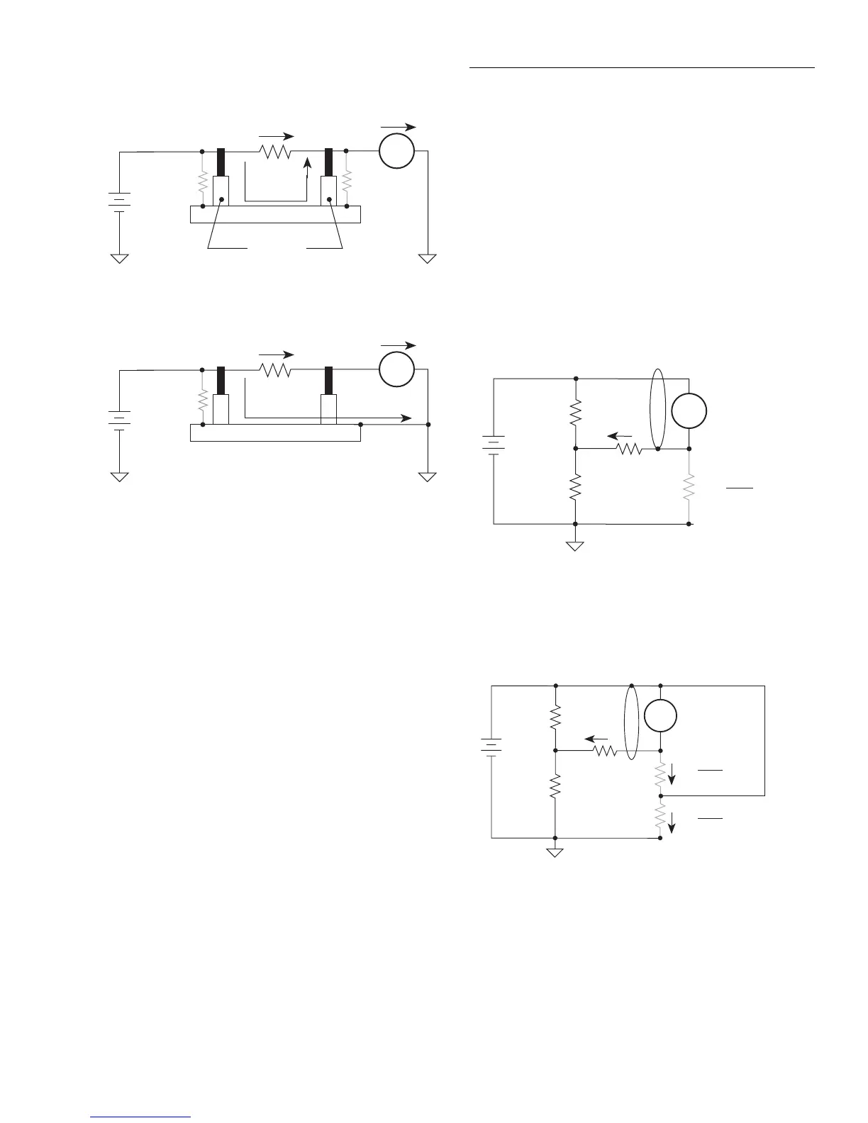
Figure 2-30A shows an unguarded floating current measure-
ment in a high impedance circuit. The goal is to measure the
current (I
R
) through resistor R. However, a leakage path (R
L
)
exists from ammeter input LO to test circuit common. Since
the ammeter drops <1mV, approximately 10V is dropped by
R
L
. The current through R
L
will be approximately 10nA
(10V/1GΩ = 10nA). Thus, the current that is measured by
the Model 6517A is the sum of the two currents (I = I
R
+
10nA). Obviously, if I
R
is a low level current, then the 10nA
leakage current will corrupt the measurement.
Figure 2-30B shows the guarded version of the same circuit.
Notice that the only difference is that the connections to the
electrometer are reversed. Resistor R
L
now represents the
leakage from ammeter input HI to ammeter input LO, and re-
sistor R
G
represents the leakage from ammeter input LO
(guard) to test circuit common. As previously mentioned, the
ammeter drops <1mV. It then follows that there is a <1mV
drop across R
L
. Thus, the current through R
L
is <1pA
(<1mV/1GΩ = <1pA). The current that is measured by the
Model 6517A is the sum of the two currents (I = I
R
+ <1pA).
The use of guarding reduced the leakage current from 10nA
to <1pA. Note that the 10nA leakage current (I
G
) from am-
meter input LO to test circuit low still exists, but it is of no
consequence since it is not measured by the Model 6517A.
I
M
= I
R
+ I
L
HI
6517A
LO
R
L1
E
R*
A
I
R
Metal Mounting Plate
Insulators
R
L2
I
L
I
M
= I
R
HI
6517A
LO
R
L1
E
R*
A
I
R
Metal Guard Plate
I
L
*R = ≥1GΩ
A. Unguarded
B. Guarded
Figure 2-29
High impedance current measurements
I = I
R
+ 10nA
R
+10V
1GΩ
I
L
=
I
R
HI
6517A
LO
A
R
L
= 10nA
10V
1GΩ
10V
A) Unguarded
I = I
R
+ <1pA
R
+10V
1GΩ
I
L
=
I
R
HI
LO
A
R
L
= <1pA
<1mV
1GΩ
10V
1GΩ
R
G
I
G
=
= 10nA
10V
1GΩ
B) Guarded
6517A
A. Unguarded
B. Guarded
Figure 2-30
Floating current measurements