Front Panel Operation
2-64
Standard Method Resistivity tests (Surface and Volume)
This test is used to measure the resistivity (surface or vol-
ume) of an insulator sample. When used with the Model
8009 Resistivity Test Fixture, the test conforms to the ASTM
D-257 standard. For detailed information on resistivity mea-
surements, refer to paragraph 2.7.2. Figures 2-33 and 2-35
show the test circuits for the respective measurement, and
Figure 2-36 shows the connections to the Model 8009. Refer
to the instruction manual for the Model 8009 to install the in-
sulator sample in the test fixture.
When this test is run, the V-Source will initially be set to
source 0V for a specified time (PRE-DISCH time) to allow
any charge to dissipate. The V-Source will then apply a spec-
ified voltage (BIAS V) to the electrodes of the test fixture for
a specified time (BIAS-TIME). This “bias” period allows
currents in the test circuit to stabilize. The V-Source then ap-
plies the test voltage (MEAS-V) and, after a specified delay
(MEAS-TIME), the Model 6517A measures the resistivity
of the sample and stores the reading in the buffer. Note that
the test voltage (MEAS-V) is typically at the same level as
the bias voltage (BIAS V).
HI
LO
6517A
Shield
Resistor
CAUTION:FOR CONTINUED PROTECTION AGAINST FIRE HAZARD,REPLACE FUSE WITH SAME TYPE AND RATING.
CAUTION:FOR CONTINUED PROTECTION AGAINST FIRE HAZARD,REPLACE FUSE WITH SAME TYPE AND RATING.
WARNING:NO INTERNAL OPERATOR SERVICABLE PARTS,SERVICE BY QUALIFIED PERSONNEL ONLY.
WARNING:NO INTERNAL OPERATOR SERVICABLE PARTS,SERVICE BY QUALIFIED PERSONNEL ONLY.
7078-TRX
Cable
INPUT
250V PEAK
COMMON
TRIGGER
LINK
IN OUT
!
LINE RATING
90-134VAC
180-250VAC
50, 60, 400HZ
55VA MAX
LINE FUSE
SLOWBLOW
1/2A, 250V
IEEE-488
(CHANGE IEEE ADDRESS
WITH FRONT PANEL MENU)
PREAMP OUT
250V PEAK
V SOURCE
LO HI
Note: Ammeter LO internally
connected to V-source LO
(see paragraph 2.9.1).
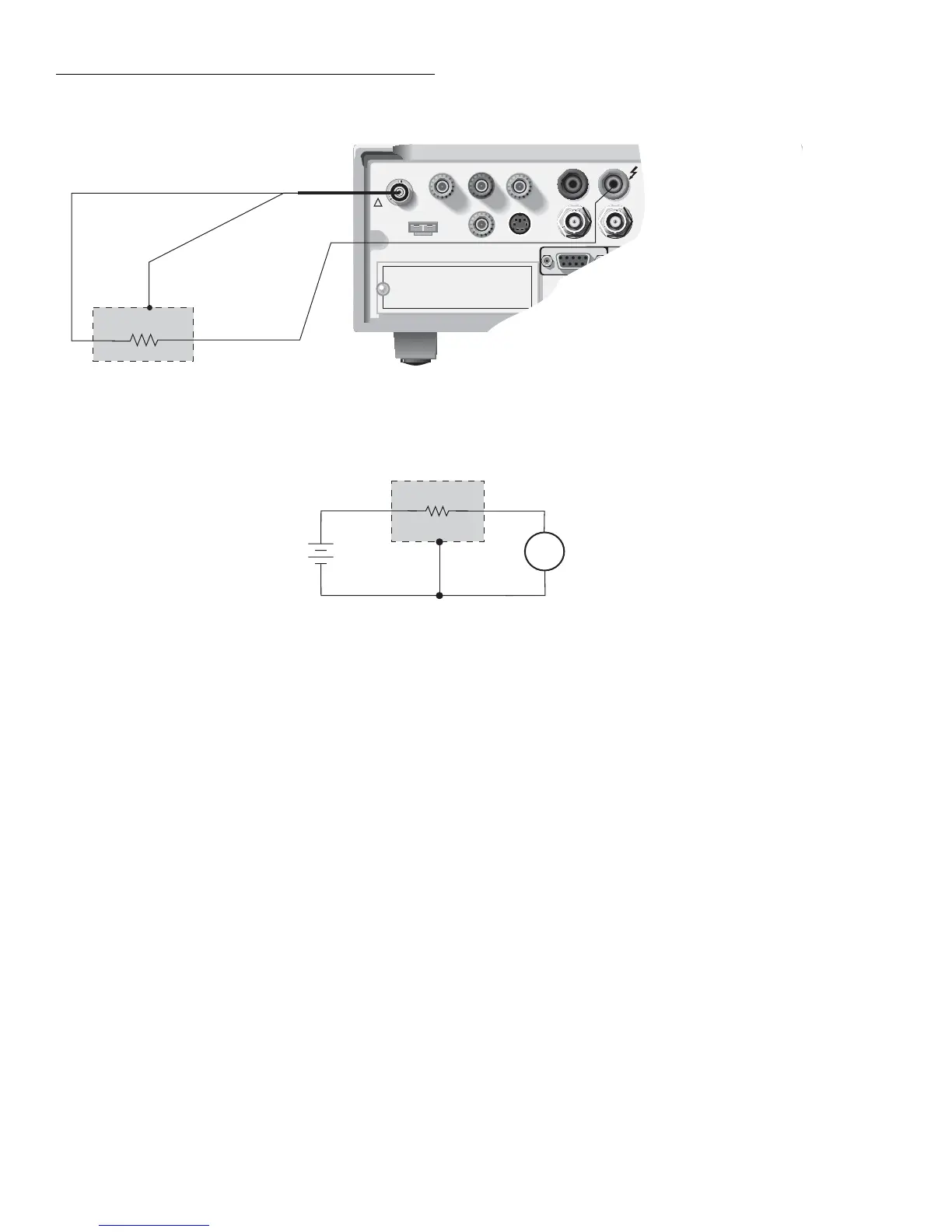
A) Connections
6517A
V-Source
A
+
-
6517A
Ammeter
B) Equivalent Circuit
HI
LO
HI
LO
Resistor
DUT
Shield
Figure 2-51
Test circuit; resistor voltage coefficient test
The Surface Resistivity Test and the Volume Resistivity Test
are selected and configured from the CONFIGURE SE-
QUENCE menu (R/RESISTIVITY; NORMAL; SURFACE
and VOLUME). See paragraph 2.14.2 for details.
Alternating Polarity Resistance/Resistivity test
The Alternating Polarity Resistance/Resistivity test is de-
signed to improve high resistance/resistivity measurements.
These measurements are prone to large errors due to back-
ground currents. By using an alternating stimulus voltage, it
is possible to eliminate the effects of these background cur-
rents. This test will measure Surface or Volume resistivity, or
Resistance, as selected in the CONFIGURE RESISTANCE
menu. For detailed information on resistivity measurements,
refer to paragraph 2.7.2. Figures 2-33 and 2-35 show the test
circuits for the respective measurements, and Figure 2-36
shows the connections to the Model 8009. Refer to the Mod-
el 8009 Instruction Manual for information on installing the
sample in the test fixture.
When this test is run, the V-Source will alternate between two
voltages (V-OFS + V-ALT) and (V-OFS - V-ALT) at timed inter-