Series 2600 System SourceMeters Reference Manual DUT Test Connections 3-9
Return to Section 3 topics 2600S-901-01 Rev. A / May 2006
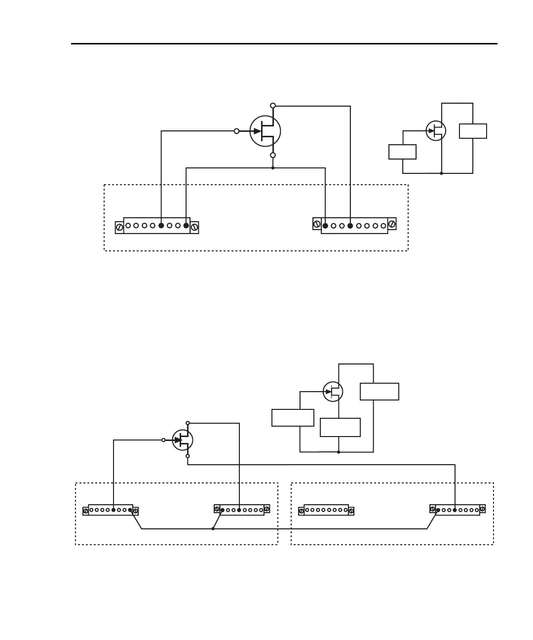
Figure 3-7
G
S
D
N-Channel
JFET
Keithley
Model 2602/2612
G
S
D
SMU A
SMU B
HI
LO
HI
LO
Equivalent Circuit
Channel
A
LO G
Lo
HI G G G
HI
SS
Channel
B
LOG
Lo
HIGGG
HI
SS
HI HILO
Two SMUs connected to a 3-terminal device (local sense)
Figure 3-8 shows how to use three SMUs to test the same 3-terminal device. The
third SMU is connected to the source (S) terminal of the JFET. This allows the
source terminal to be biased above signal low. Setting this SMU to output 0V
effectively connects the source terminal of the JFET to signal low.
Figure 3-8
G
S
D
N-Channel
JFET
Keithley Model 2602/2612-1
Channel
A
LO G
Lo
HI G G G
HI
SS
Channel
B
LOG
Lo
HIGGG
HI
SS
HI HI
Keithley Model 2602/2612-2
Channel
A
LO G
Lo
HI G G G
HI
SS
Channel
B
LOG
Lo
HIGGG
HI
SS
HI
G
S
D
Equivalent Circuit
SMU B
Unit #1
HI
LO
SMU A
Unit #2
HI
LO
SMU A
Unit #1
HI
LO
Three SMUs connected to a 3-terminal device (local sense)
 Loading...


