8-8 Source-Measure Concepts Series 2600 System SourceMeters Reference Manual
2600S-901-01 Rev. A / May 2006 Return to Section 8 topics
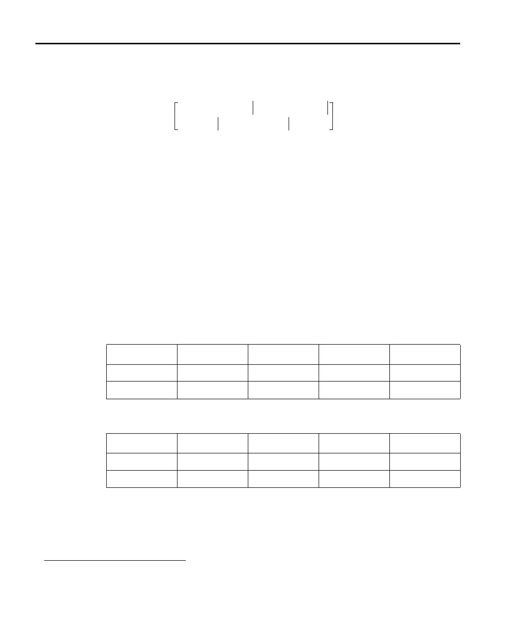
Maximum duty cycle equation
1,
2
DC
MAX
P
CS
T
DER
–()V
OA
V
B
–()V
B
()–
V
OA
V
P
–()I
P
()
-------------------------------------------------------------------------------------------
100×
2
≤
NOTE When attempting to determine the maximum duty cycle where the
off state will be 0V or 0A:
•I
B
is 0
•I
P
and V
P
are the voltage and current levels when the
SourceMeter is on.
NOTE This maximum duty cycle equation is an approximation. In general,
if the duty cycle calculation yields a number > 90% then DC under
those conditions should not cause the SourceMeter to overheat.
However, if the calculation yields a number < 10%, the calculated
duty cycle should not be exceeded by more than 0.5% to avoid
potential overheating.
Model 2601/2602 Maximum Duty Cycle equation constants
Constant 100mV range 1V range 6V range 40V range
P
HS
56 56 56 56
V
OA
18 18 18 56
Model 2611/2612 Maximum Duty Cycle equation constants
Constant 200mV range 2V range 20V range 200V range
P
HS
56 56 56 48
V
OA
38 38 38 222
1. Equations apply to both channels, sinking or sourcing power simultaneously.
2. If a duty cycle less than 100% is required to avoid overheating, the maximum on time must be less than
10 seconds.
 Loading...


